Removal and Replacement Procedures
Maintenance and Service Guide 5–67
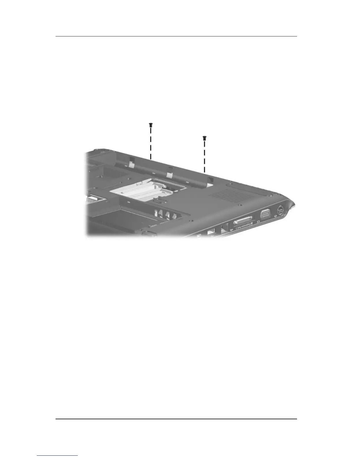
2. Turn the computer upside down with the front toward you.
3. Remove the two silver Phillips PM2.5×5.0 screws that secure
the top cover rear strip to the computer.
Removing the Base Enclosure Trim Screws