Removal and Replacement Procedures
Maintenance and Service Guide 5–71
❏ Display assembly (Section 5.12)
❏ Top cover (Section 5.13)
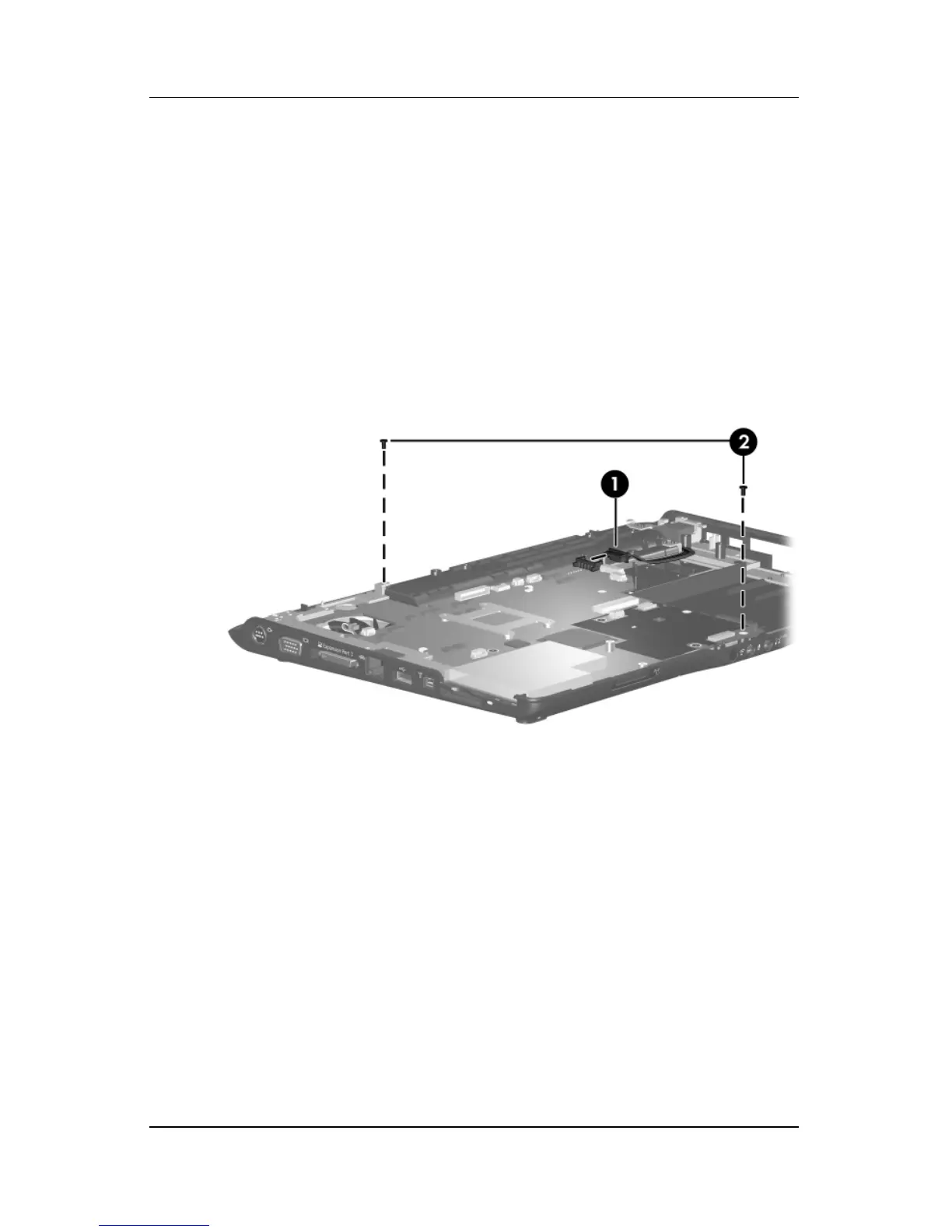
2. Turn the top cover right-side up with the front toward you.
3. Disconnect the power connector cable 1 from the
system board.
4. Remove the two Phillips PM2.5×5.0 screws 2 that secure
the system board to the top cover.
Removing the System Board Screws