10
Cooling requirements
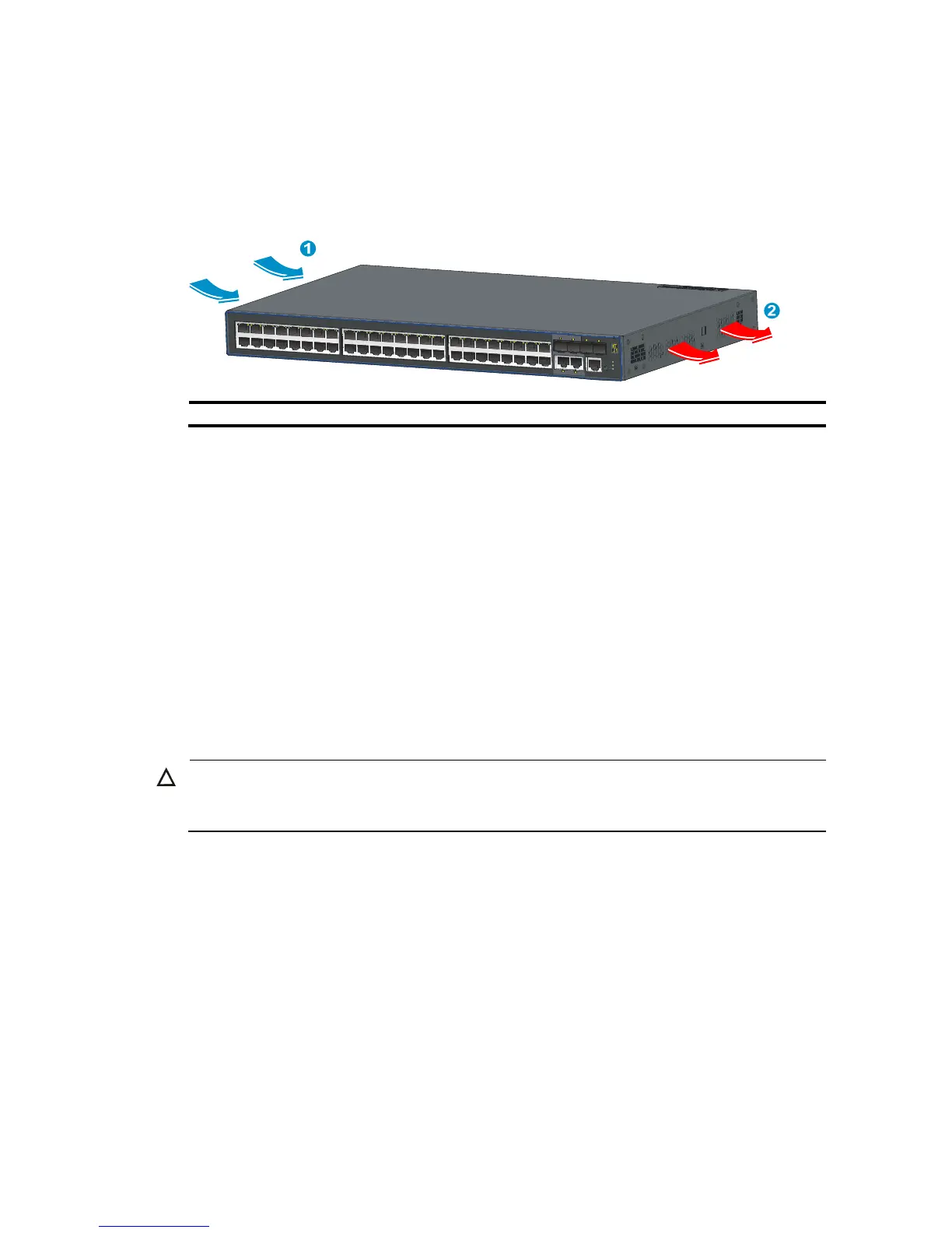
The built-in fans in the 3600 v2 switches blow air from the left to the right of the chassis for heat
dissipation, as shown in Figure 15.
Figure 15 Airflow through the 3600 v2 switches
(1) Air intake (2) Air exhaust
For adequate heat dissipation, plan the installation site according to the airflow of your switch, and
adhere to the following requirements:
• Leave a clearance of at least 10 cm (3.94 in) around the air intake and exhaust vents.
• Consider the heat dissipation of the installation site when determining air-conditioning
requirements to ensure that cool air can enter the switch.
• Make sure the hot air generated by equipment at the bottom of the rack is not drawn in the intake
of the equipment above.
• The installation site has a good cooling system.
Laser safety
The 3600 v2 switches are Class 1 laser devices.
CAUTION:
Do not stare into any fiber port when the switch has power. The laser li
 Loading...


