31
2 System Board - (SiS Chipset) (Part Number: D4051-63001)
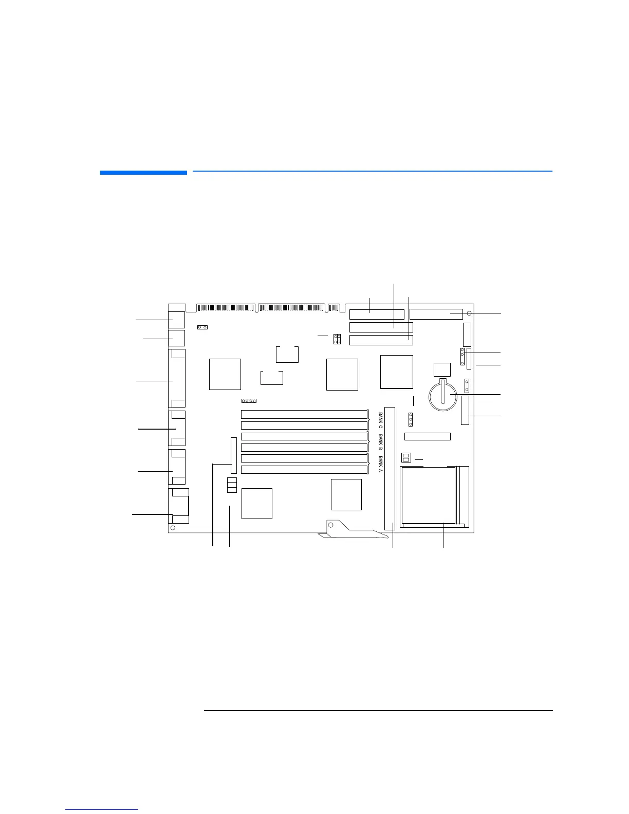
System Board Physical Layout
System Board Physical Layout
The following system board diagram will help you identify where the
different components and connections are located on the board. Refer to the
section System Board Switches and Jumpers (D4051-63001) on page 38 for
switches and jumper settings.
*
Multi-purpose Security
Feature Switch
VESA Feature Connector
Video
Serial B
Serial A
Parallel
Keyboard
Mouse
Processor Socket
Backplane Connector Floppy Disk Drive Connector
CD-ROM Connector (IDE Channel 2)
HDD Connector (IDE Channel 1)
Space-bar Power-on
CPU Bus Frequency
Main Memory Sockets
Cache Jumper
CPU Core
Frequency
Second Level
Cache Memory Socket
Power
Connector 3.3 V
Power Connector
Ext. Battery
Connector
Status Panel VE
Battery
SiS 6205
Graphics
controller
SiS 5512
Data Buffer
Super I/O
Little
Ben
BIOS
Flash
SiS 5513
PCI/ISA
bridge
C2
C1
B2
B1
A2
A1
JP4
J7
2
1
4
3
J1
J2
J6
1
2
3
SW2
1
2
SW1
1
2
3
J15 Product ID flag
SiS 5511
Memory
controller
 Loading...