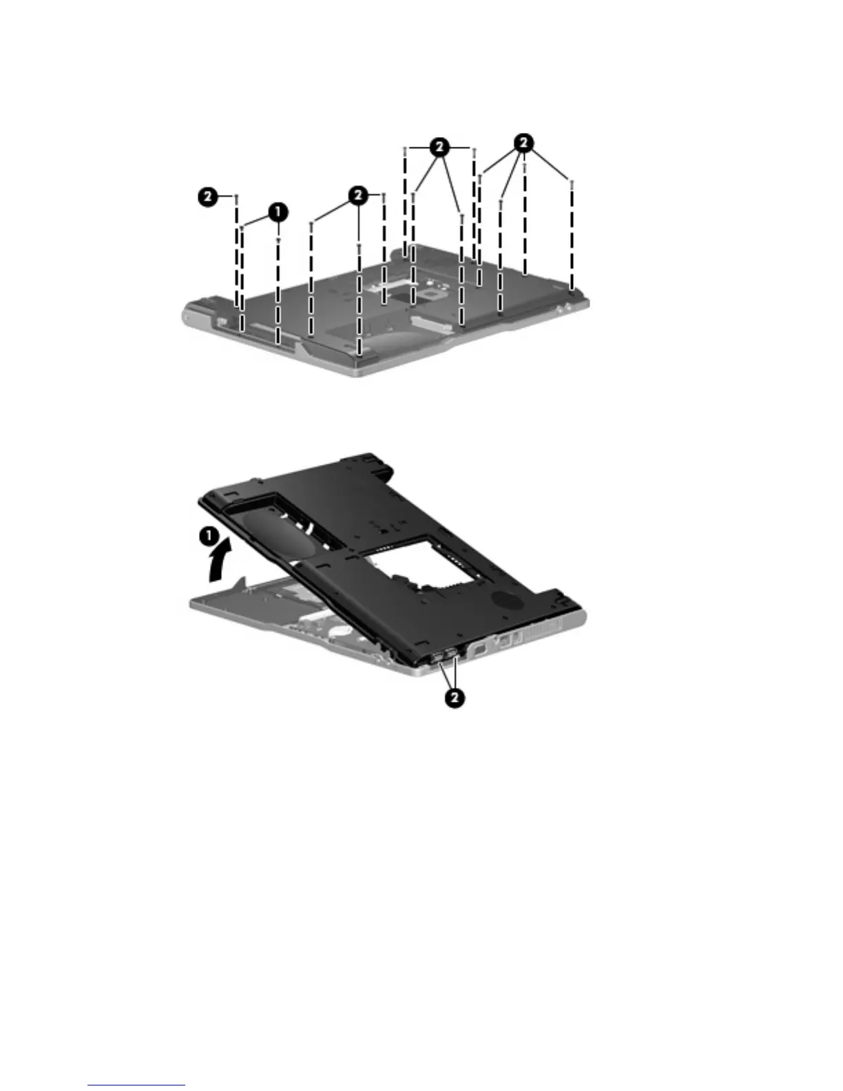
3. Remove the two Phillips PM2.0×3.0 screws (1) and the twelve Phillips PM2.0×9.0 screws (2) that
secure the base enclosure to the computer.
4. Lift the left side of the base enclosure (1) until the USB connectors (2) disengage from their openings
in the base enclosure.
5.
Remove the base enclosure.
Reverse this procedure to install the base enclosure.
Component replacement procedures 53

 Loading...