Model 5328A
Operation
*f. START CLOCK. A "phantom" function located
1
switch position clockwise from STOP.
Totalizes the internal
10
MHz clock +N where N
is
selected by the RESOLUTION switch
(N
110).
The scaled output (i.e.,
10
MHz tN)
is
available at the time base out rear panel
connector.
*g. DVM/A. A "phantom" function located
2
switch positions clockwise from STOP. Used
for scaling DVM measurements. Counter displays DVM/freq A where freq A
fO
MHz.
N selects the number of events at A over which the measurement
is
made.
*h. DVM, A+B. A "phantom" function located 3 switch positions to the right of STOP. The
voltage at the DVM terminals
is
integrated over the synchronized time interval defined
by events at channels A and B.
Units of the displayed reading are volteseconds.
FREQ A. Sets counter to measure frequency at channel A.
PER A. Sets counter to measure period at channel A.
PER AVG A. Sets counter to make a period average measurment of thesignal at channel
A. The number of periods over which the average measurement is made
is
determined
by N, selected by the RESOLUTION switch.
RATIO B/A. Sets counter to measure the ratio of the frequency at channel B to the
frequency at channel A.
T.I. A--B. Sets counter to make a time interval measurement. Start signal
is
applied to
channel A and the stop signal is applied to channel
B.
T.I. AVG A4B. Sets counter to make a time interval average measurement of the time
interval from A TO B. The number of time intervals over which the average
measurement is made
is
determined by N, selected by the RESOLUTION switch.
EVENTS
C,
A--B. Sets the counterto totalize the number of eventsat thechannel C input
during the synchronized time interval determined by inputs to channels A and B.
*"phantom" functions which, due to relatively limited use, are not labeled on the 5328A front
panel.
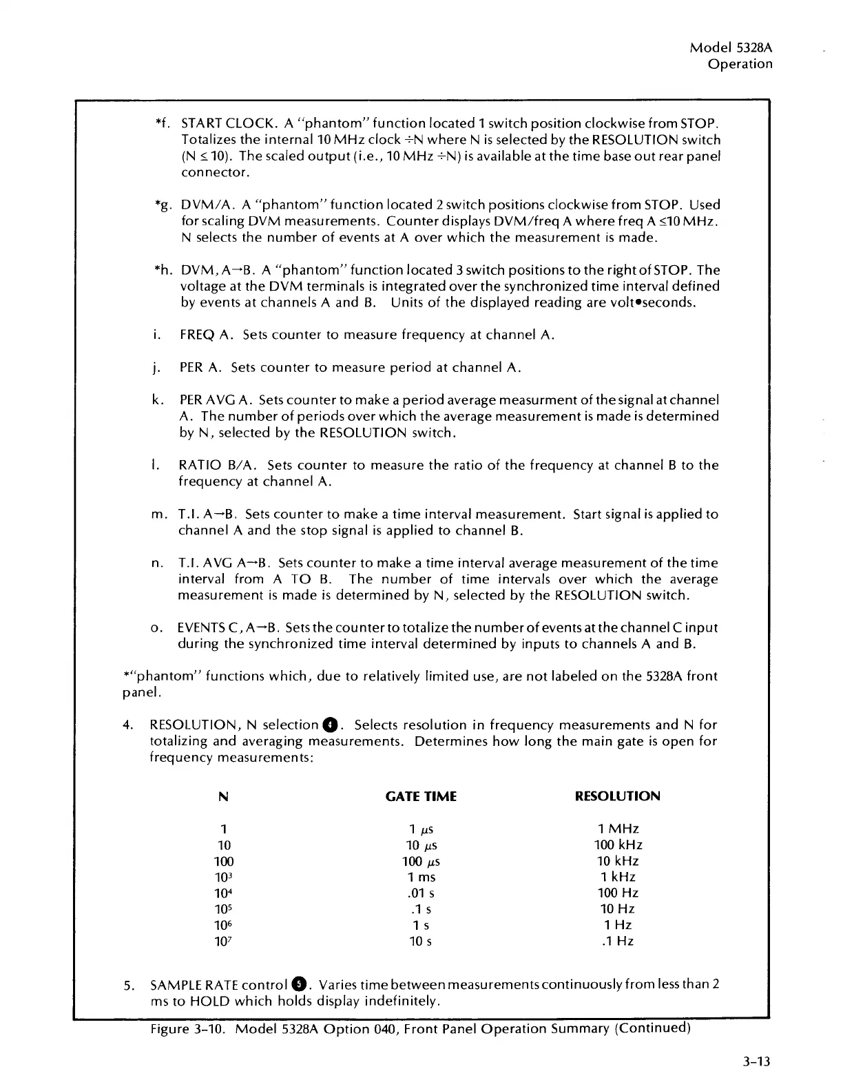
4.
RESOLUTION, N selection
0.
Selects resolution in frequency measurements and N for
totalizing and averaging measurements. Determines how long the main gate
is
open for
frequency measurements:
N
GATE TIME RESOLUTION
1
MHz
100
kHz
10
kHz
1
kHz
100
Hz
10
Hz
1
Hz
.I
Hz
5.
SAMPLE RATE control
@.
Varies time between
measurementscontinuously
from less than 2
ms to HOLD which holds display indefinitely.
Figure
3-10.
Model 5328A Option
040,
Front Panel Operation Summary (Continued)
Artisan Technology Group - Quality Instrumentation ... Guaranteed | (888) 88-SOURCE | www.artisantg.com