Model 5328A
Operation
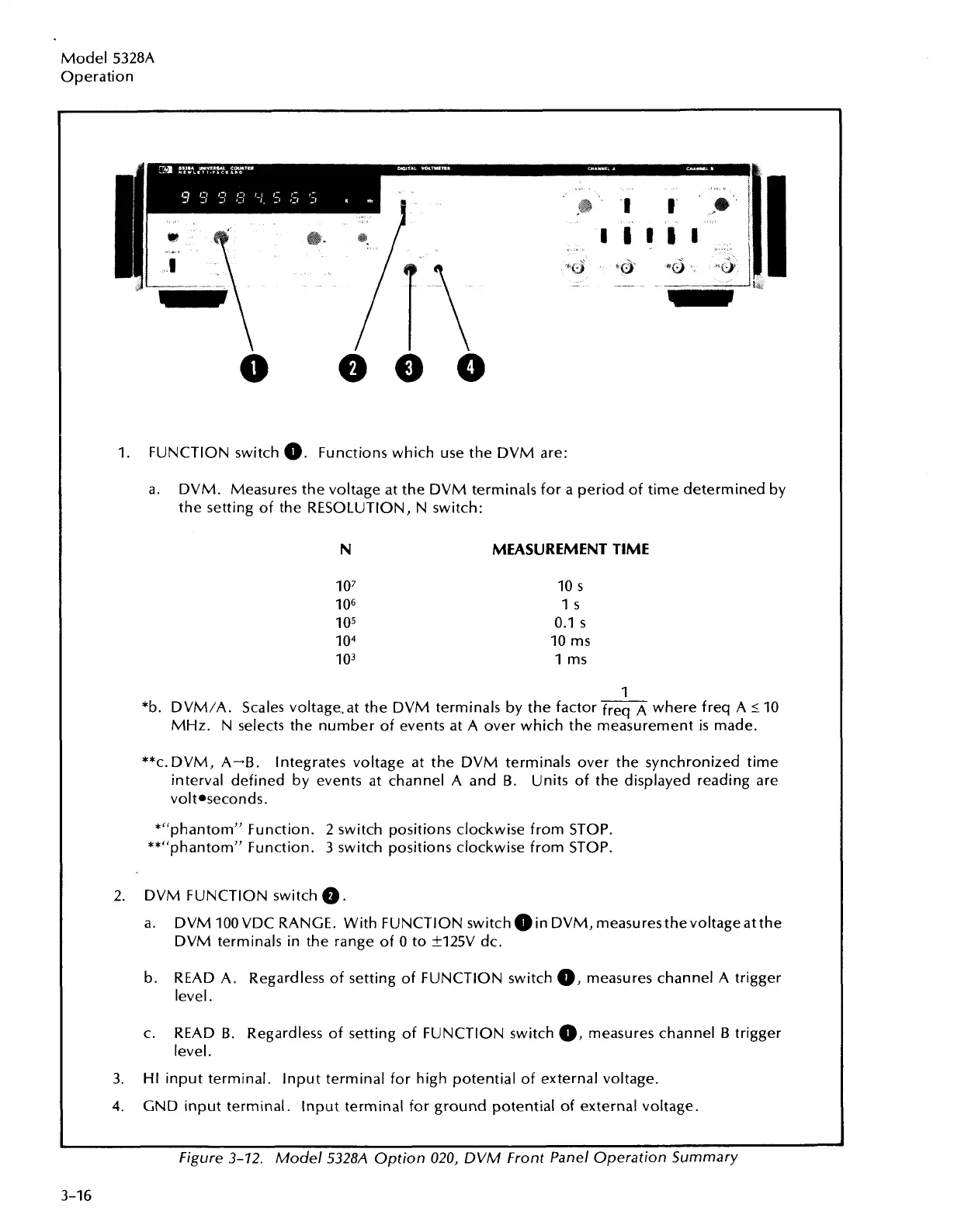
1. FUNCTION switch
0.
Functions which use the DVM are:
a.
DVM. Measures the voltage at the DVM terminals for a period of time determined by
the setting of the RESOLUTION, N switch:
N
MEASUREMENT TIME
1
*b.
DVM/A. Scales voltagesat the DVM terminals by the factor
freq
where freq A
L
10
MHz. N selects the number of events at A over which the measurement
is
made.
**c.DVM, A+B.
Integrates voltage at the DVM terminals over the synchronized time
interval defined by events at channel A and
B.
Units of the displayed reading are
volt*seconds.
*"phantomn Function. 2 switch positions clockwise from STOP.
**"phantomw Function. 3 switch positions clockwise from STOP.
2. DVM FUNCTION switch
@.
a. DVM 100VDC RANGE. With FUNCTION switch
0
in DVM, measures thevoltageat the
DVM terminals in the range of 0 to +125V dc.
b.
READ A. Regardless of setting of FUNCTION switch
0,
measures channel A trigger
level.
c.
READ
B.
Regardless of setting of FUNCTION switch
0,
measures channel
B
trigger
level.
3.
HI input terminal. lnput terminal for high potential of external voltage.
4.
GND input terminal. lnput terminal for ground potential of external voltage.
Figure
3-72.
Model
5328A
Option
020,
DVM Front Panel Operation Summary
Artisan Technology Group - Quality Instrumentation ... Guaranteed | (888) 88-SOURCE | www.artisantg.com