Model 5328A
Operation
INPUT
AC.DC
1
1
ATTEN
A
XI, X10, XlOO
*
COM A
l NPUT
AC-DC
ATTEN
B
-
XI. X10, XlOO
T
TRIGGER LEVEL
&
SLOPE
"A"
TRIGGER LEVEL
& SLOPE
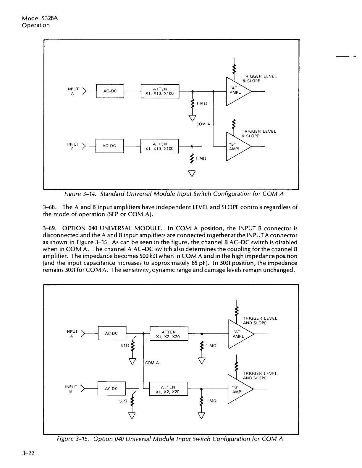
Figure 3-14. Standard Universal Module lnput Switch Configuration for COM
A
3-68. The A and
B
input amplifiers have independent LEVEL and SLOPE controls regardless of
the mode of operation
(SEP
or COM A).
3-69.
OPTION 040 UNIVERSAL MODULE. In COM A position, the INPUT
B
connector
is
disconnected and the A and
B
input amplifiers are connected together at the INPUTA connector
as
shown in Figure 3-15. As can be seen in the figure, the channel
B
AC-DC switch
is
disabled
when in COM A. The channel A AC-DC switch also determines the coupling for the channel
B
amplifier. The impedance becomes 500 kR when in COM A and in the high impedance position
(and the input capacitance increases to approximately 65 pF). In 50R position, the impedance
remains 50R for COM A. The sensitivity, dynamic range and damage levels remain unchanged.
INPUT
A
)-C
AC DC
TRIGGER LEVEL
AND SLOPE
ATTEN "A"
XI. X2. X20
Figure 3-75. Option 040 Universal Module lnput Switch Configuration for COM
A
Artisan Technology Group - Quality Instrumentation ... Guaranteed | (888) 88-SOURCE | www.artisantg.com