EasyManua.ls Logo

HP 8753D Option 011

HP 8753D Option 011
398 pages
To Next Page IconTo Next Page
To Previous Page IconTo Previous Page
Loading...
A17
Motherboard
Assembly
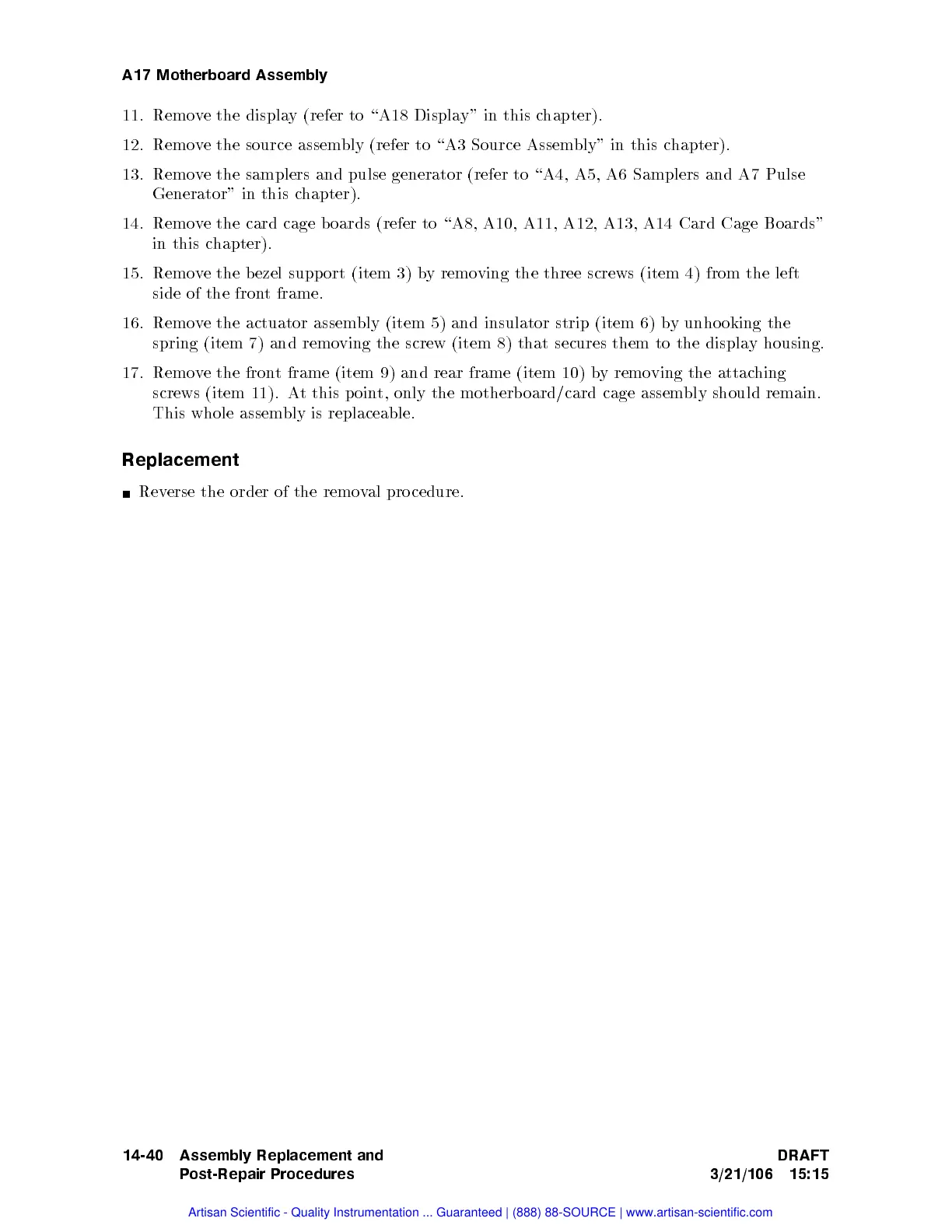
11.
Remo
v
e
the
displa
y
(refer
to
\A18
Display"
in this
chapter).
12.
Remov
e the
source assem
bly (refer
to \A3
Source Assem
bly" in
this
c
hapter).
13. Remo
ve
the samplers
and
pulse
generator
(refer
to
\A4,
A5,
A6
Samplers
and
A7
Pulse
Generator"
in
this
c
hapter).
14.
Remov
e the
card cage
b
oards
(refer
to
\A8,
A10,
A11,
A12,
A13,
A14
Card
Cage
Boards"
in
this
c
hapter).
15.
Remo
v
e
the
b
ezel supp
ort (item
3) b
yremo
ving
the
three
screws
(item
4)
from
the
left
side
of the
front
frame.
16.
Remo
v
e
the
actuator
assem
bly
(item
5)
and
insulator
strip
(item 6)
by
unhooking
the
spring
(item
7)
and
remo
ving
the screw
(item 8)
that secures
them
to
the
displa
y
housing.
17.
Remov
e
the
fron
t
frame
(item
9)
and
rear
frame
(item
10)
b
y
remo
ving
the
attac
hing
screws
(item
11).
A
t
this
p
oin
t,
only
the
motherb
oard/card
cage assem
bly should
remain.
This
whole
assem
bly
is
replaceable.
Replacement
Rev
erse the
order of
the
remo
v
al
pro
cedure.
14-40 Assembly Replacement and
Post-Repair Procedures
DRAFT
3/21/106 15:15
Artisan Scientific - Quality Instrumentation ... Guaranteed | (888) 88-SOURCE | www.artisan-scientific.com

Table of Contents

Related product manuals