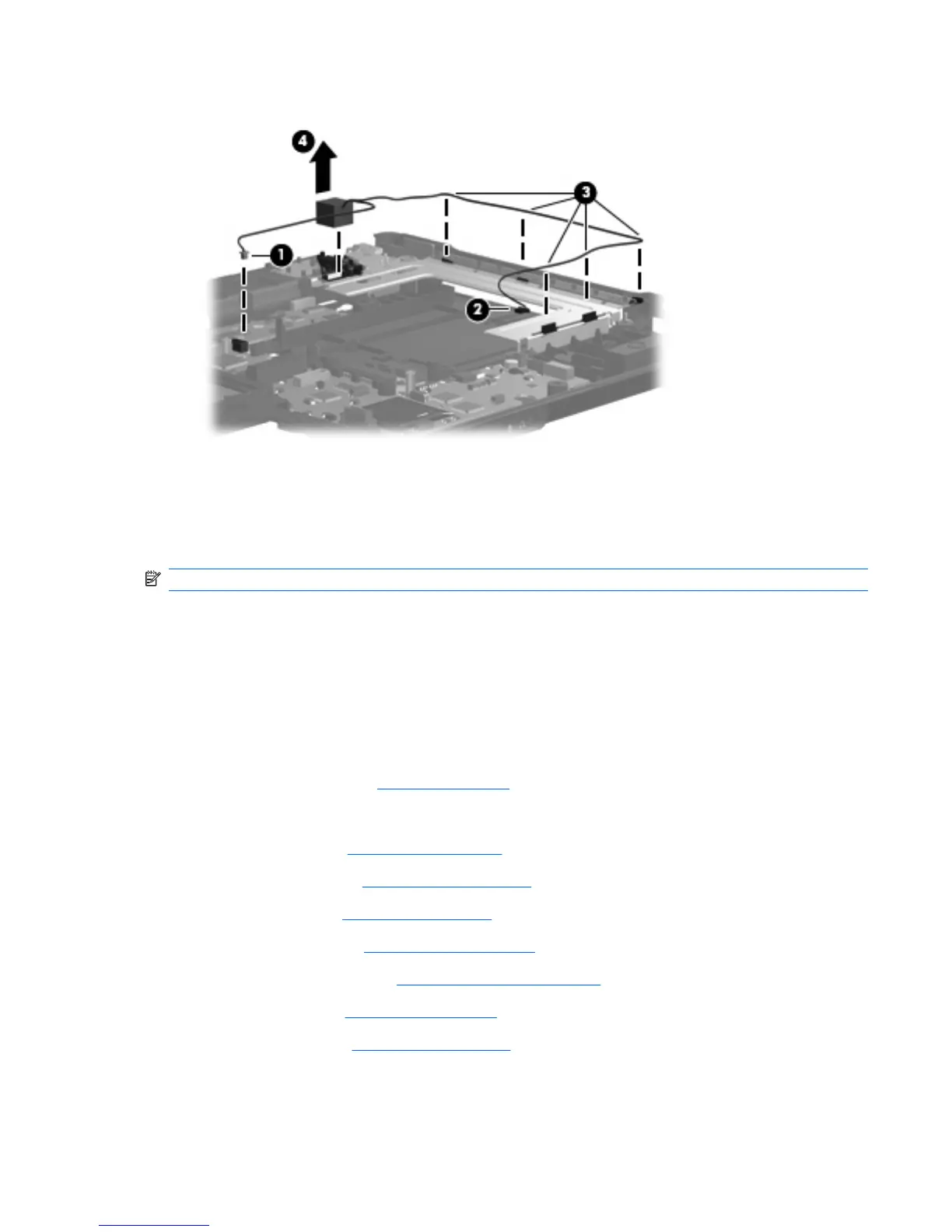
3. Release the RJ-11 connector (4) from the clip built into the base enclosure.
4. Remove the modem module cable.
Reverse this procedure to install the modem module cable.
Serial connector and cable
NOTE: The serial connector and cable is included in the Cable Kit, spare part number 487138-001.
Before removing the serial connector and cable, follow these steps:
1. Shut down the computer. If you are unsure whether the computer is off or in Hibernation, turn the
computer on, and then shut it down through the operating system.
2. Disconnect all external devices connected to the computer.
3. Disconnect the power from the computer by first unplugging the power cord from the AC outlet and
then unplugging the AC Adapter from the computer.
4. Remove the battery (see
Battery on page 46).
5. Remove the following:
a. Hard drive (see
Hard drive on page 52)
b. Optical drive (see
Optical drive on page 55)
c. Keyboard (see
Keyboard on page 60)
d. Switch cover (see
Switch cover on page 65)
e. Display assembly (see
Display assembly on page 74)
f. Top cover (see
Top cover on page 80)
g. Rear cover (see
Rear cover on page 91)
Component replacement procedures 95

 Loading...