7-4 www.hp.com Technical Reference Guide
Power and Signal Distribution
7.2.3 CMT Power Distribution
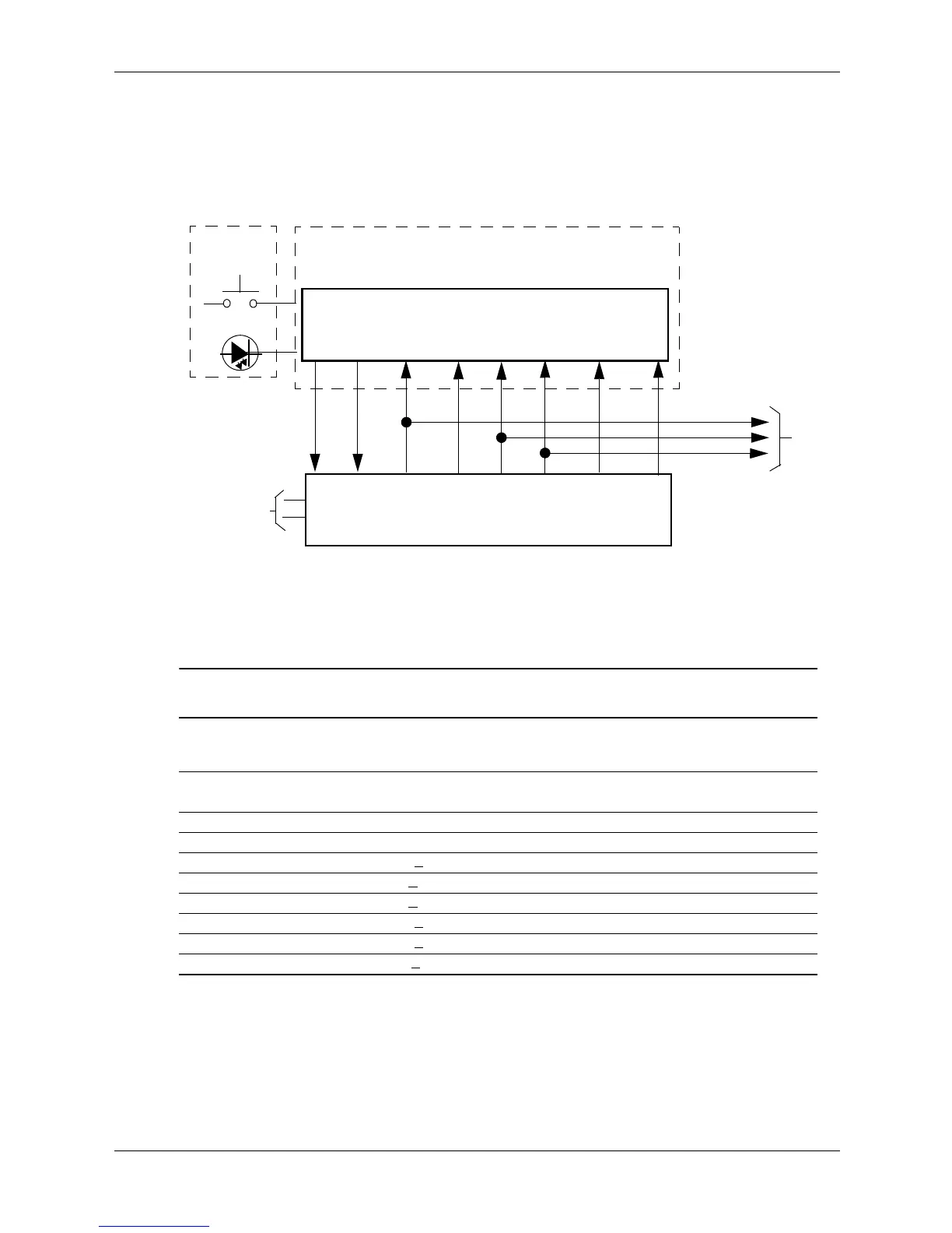
The CMT form factor uses a power supply unit internal to the system chassis. Figure 7-4 shows
the block diagram for power generation in the CMT.
Figure 7-4. CMT Power Generation, Block Diagram
Table 7-3 lists the specifications for the 365-watt power supply used in the CMT form factor.
NOTES:
Total continuous output power should not exceed 365 watts. Maximum surge power should not exceed 385 watts.. Maximum
combined power of +5 and +3.3 VDC is 160 watts.
[1] Minimum loading requirements must be met at all times to ensure normal operation and specification compliance.
[2] Maximum surge duration for +12Vcpu is 1 second with 12-volt tolerance +/- 10%.
Table 7-3.
CMT 365-Watt Power Supply Unit Specifications
Range or
Tolerance
Min.
Current
Loading [1]
Max.
Current
Surge
Current [2]
Max.
Ripple
Input Line Voltage:
115–230 VAC (auto-ranging) 90–264 VAC -- -- -- --
Line Frequency 47–63 Hz -- -- -- --
Input (AC) Current -- -- 6.0 A -- --
+3.3 VDC Output +
4 % 0.10 A 24.0 A 24.0 A 50 mV
+5.08 VDC Output +
3.3 % 0.30 A 19.0 A 19.0 A 50 mV
+5.08 AUX Output + 3.3 % 0.00 A 3.00 A 3.00 A 50 mV
+12 VDC Output +
5 % 0.20 A 12.0 A 14.5 A 120 mV
+12 VDC Output (Vcpu) +
5 % 0.00 A 14.5 A 17.5 A 200 mv
-12 VD C Output +
10 % 0.00 A 0.15 A 0.15 A 200 mV
System Board
Power Supply
Power On
CPU, slots, Chipsets, Logic,
Front Bezel
& Voltage Regulators
Unit
Fan
PS On
+5 VDC
+12 VccP
Power Button
Spd [1]
+12 VDC
-12 VDC
+3.3 VDC
Drives
+3.3 VDC
+5 VDC
+12 VDC
90 - 264 VAC
NOTE:
[1] Not present on CMT.
5 AUX
 Loading...