Installing the switch | 38
n See the Transceiver Guide.
n See the supported transceivers information in the Data Sheet for your switch model.
Hot swapping SFP/SFP+/SFP28/SFP56 transceivers
Supported SFP/SFP+/SFP28/SFP56 transceivers that you can install in your HPEAruba Networking switch can be “hot
swapped”– removed and installed while the switch is receiving power. However, disconnect the network cables from
the SFP/SFP+/SFP28/SFP56 transceivers before hot-swapping them.
When you replace a SFP/SFP+/SFP28/SFP56 transceiver with another transceiver of a different type, the switch may
retain selected port-specific configuration settings that were configured for the replaced unit. Be sure to validate or
reconfigure port settings as required.
SFP/SFP+/SFP28/SFP56 connections to devices with fixed speed/duplex configurations
When connecting a device to your switch port that contains a SSFP/SFP+/SFP28/SFP56 transceiver, the speed and
duplex settings of the switch port and the connected device must match. Otherwise, the device may not link
properly—you may not get a link. For some older network devices, the default speed/duplex settings may be
predefined such that they are set differently from the default configuration of your switch. (For example, 1000
Mbps/Full Duplex.) These setting differences may also apply to some older Hewlett Packard Enterprise devices.
Because of these default speed/duplex considerations, make sure that devices connected to your
SFP/SFP+/SFP28/SFP56 ports are properly configured. At a minimum, make sure the configurations match.
Sample network topologies
This section shows a few sample network topologies in which the switch is implemented.
The switch is designed to be used primarily as a desktop switch. End nodes, printers and other peripherals, and
servers are directly connected, as shown in the following illustration. Notice that the end node devices are
connected to the switch by straight-through or crossover twisted-pair cables. Either cable type can be used because
of the IEEE Auto MDI/MDI-X features on the switch.
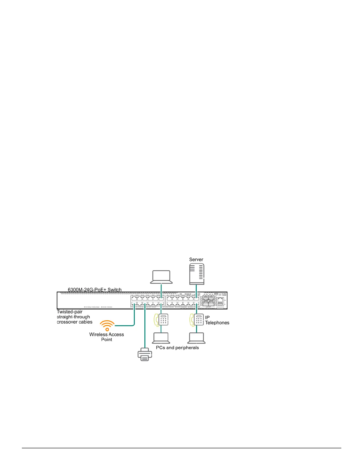
Figure 11 Example as a Desktop Switch Implementing PoE
This illustration is an example of the switch being configured to supply PoE power to end devices such as IP
telephones and wireless access points (WAPs).
As shown in this figure, the IP telephones can be connected in line, that is, between the switch and the end device, in
this case a PC. The IP telephones in this illustration have two ports, one in and one out. Therefore the phone
receives voice data and power from the switch, and the PC can send and receive data through the phone to the
switch.