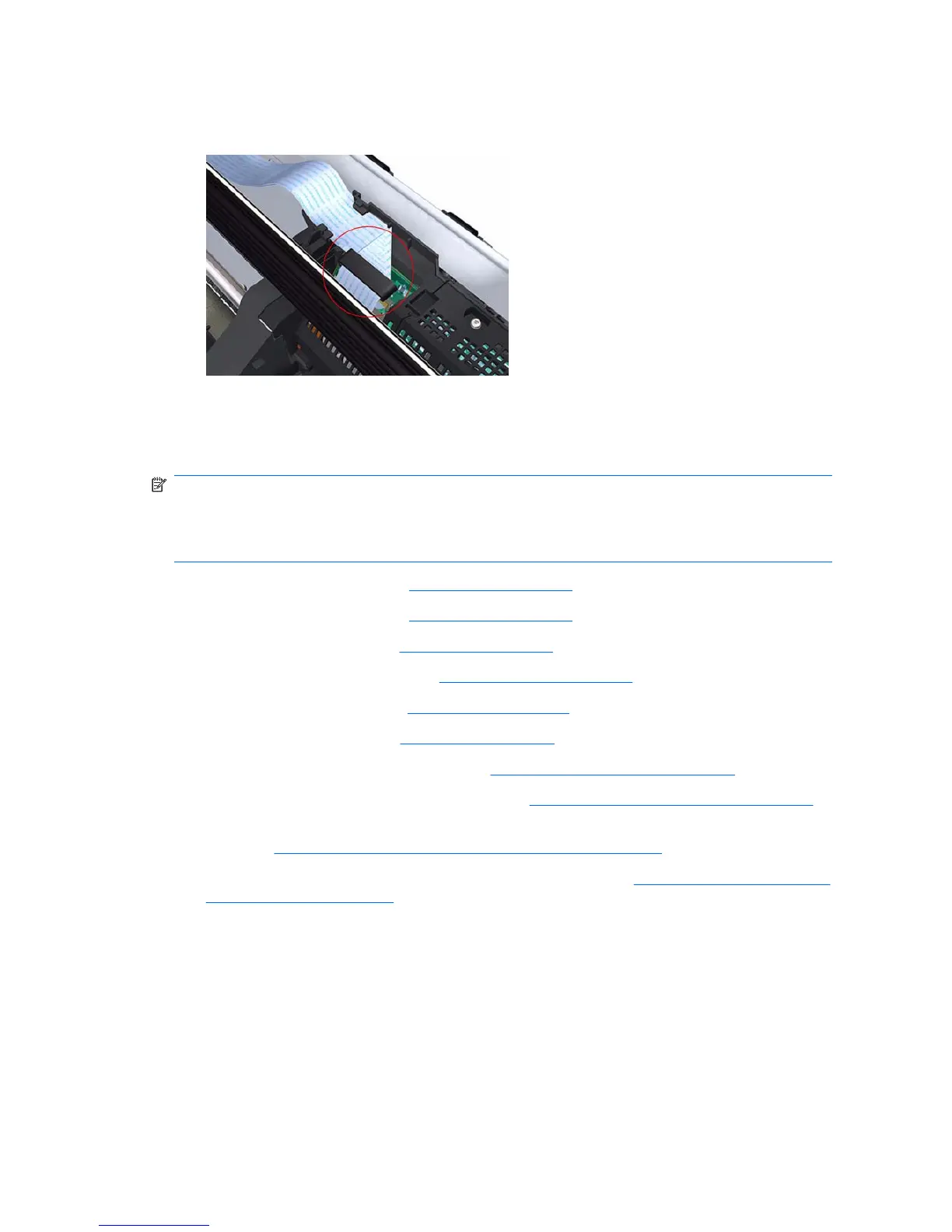
3. Make sure that the Ferrite Core is correctly positioned so that the small cover of the Carriage PCA
closes correctly to avoid possible friction damage to the Trailing Cable during operation of the
printer.
Carriage Assembly (with or without Trailing Cable)
Removal
NOTE: Switch off the printer and remove the power cable.
NOTE: If you replace the Carriage Assembly with service parts Q6683-60231 (24 inch) or
Q6687-60087 (44 inch) that include a Trailing Cable, remember to remove the Trailing Cable with the
Carriage Assembly.
1. Remove the Front Cover (refer Front Cover on page 177).
2. Remove the Right Cover (refer
Right Cover on page 185).
3. Remove the Left Cover (refer
Left Cover on page 188).
4. Remove the Cutter Assembly (refer
Cutter Assembly on page 199).
5. Remove the Front Panel (refer
Front Panel on page 203).
6. Remove the Top Cover (refer
Top Cover on page 205).
7. Remove the Window Position Sensor (refer
Window Position Sensor on page 208).
8. Remove the Ink Supply Tubes Support Rail (refer
Ink Supply Tubes Support Rail on page 209).
9. Manually uncap the Service Station before removing the Encoder Strip (with spring and attachment
nut) (refer Encoder Strip (with spring and attachment nut) on page 231).
10. Remove the Encoder Strip (with spring and attachment nut) (refer
Encoder Strip (with spring and
attachment nut) on page 231).
11. If necessary manually move the Carriage Assembly fully right into the docking station.
244 Chapter 6 Removal and Installation ENWW
 Loading...