39. Remove the Scan Side Panel.
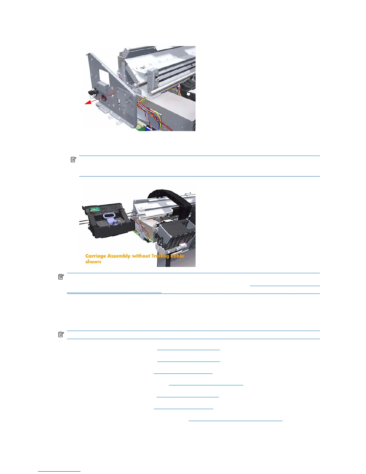
40. Carefully slide the Carriage Assembly and Belt Assembly out of the printer (and the Trailing Cable
if you are removing it with the Carriage Assembly).
NOTE: Before you reinstall the Carriage Assembly use an alcohol dampened cloth to remove all
traces of residual adhesive (remaining from the double sided pads removed in step 14) from the
printer before applying new pads in the same positions as the original pads.
NOTE: When you finish installing or replacing this component, you must perform the necessary
Service Calibrations. To find which calibrations you must perform, refer to
Service Calibration Guide to
Removal and Installation on page 170.
Carriage Rear Bushing
Removal
NOTE: Switch off the printer and remove the power cable.
1. Remove the Front Cover (refer Front Cover on page 177).
2. Remove the Right Cover (refer
Right Cover on page 185).
3. Remove the Left Cover (refer
Left Cover on page 188).
4. Remove the Cutter Assembly (refer
Cutter Assembly on page 199).
5. Remove the Front Panel (refer
Front Panel on page 203).
6. Remove the Top Cover (refer
Top Cover on page 205).
7. Remove the Window Position Sensor (refer
Window Position Sensor on page 208).
8. Remove the Ink Supply Tubes Support Rail (refer
Ink Supply Tubes Support Rail on page 209).
254 Chapter 6 Removal and Installation ENWW
 Loading...