Do you have a question about the HP DL385-G7 and is the answer not in the manual?
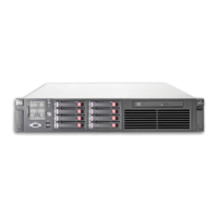
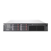
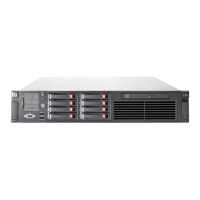
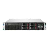
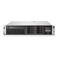
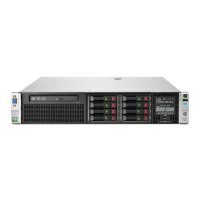
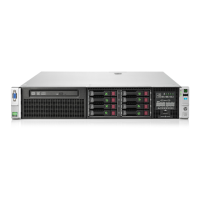
Identifies and describes the physical components located on the front panel of the server.
Details the status indicators (LEDs) and control buttons on the server's front panel.
Explains the different LEDs present on the Systems Insight Display.
Correlates illuminated system LEDs with specific health status indicators.
Identifies and describes the physical components located on the rear panel of the server.
Details the status indicators (LEDs) and control buttons on the server's rear panel.
Specifies the configurations and capabilities of non-hot-plug PCI riser board slots.
Identifies the main components and connectors on the server's system board.
Explains the function and default settings of system board switches.
Describes the Non-Maskable Interrupt (NMI) feature for system diagnostics.
Shows the location and numbering of the server's DIMM (memory) slots.
Illustrates the numbering scheme for the server's hard drive bays.
Details the status indicators (LEDs) for SAS and SATA hard drives.
Interprets the combined status of SAS/SATA drive LEDs to indicate drive health.
Explains the LEDs associated with the PCI riser cage assembly.
Details the status indicators (LEDs) for the server's battery pack.
Explains the status indicators (LEDs) for the Flash-Backed Write Cache module.
Covers the operation, installation, and configuration of hot-plug fans.
Provides instructions for turning the server on.
Details the steps required for safely shutting down the server.
Procedure for sliding the server out of its rack for servicing.
Steps to remove the server's outer cover for internal access.
Steps to reinstall the server's outer cover after servicing.
Procedure to remove the retainer for full-length expansion boards.
Steps to remove the PCI riser assembly from the server.
Steps to install the PCI riser assembly into the server.
Procedure to reinstall the retainer for full-length expansion boards.
Methods to gain access to the server's rear panel connections.
Instructions for managing cables using a left-hand swing cable arm.
Instructions for managing cables using a right-hand swing cable arm.
Procedure for removing the server's air baffle.
Details on how hot-plug fans function and their operational configurations.
Information on HP Care Pack services for server installation and support.
Guidance and resources for planning server rack installations.
Requirements for server placement and environmental conditions.
Specifies clearances needed for servicing and proper airflow.
Defines the acceptable operating temperature ranges for the server.
Outlines electrical power considerations and guidelines for installation.
Details necessary electrical grounding procedures for safety and operation.
Safety precautions related to rack installation, stability, and component handling.
Lists the items included in the server packaging for installation.
General guidance on installing optional hardware components.
Step-by-step guide for mounting the server securely into a rack.
Instructions and methods for installing a supported operating system.
Initial server startup procedures and basic configuration steps.
Information on how to register the server with HP for support and warranty.
General advice for installing multiple hardware options and streamlining the process.
Details on installing or replacing server processors, including single and dual configurations.
Guide for installing and enabling a Trusted Platform Module (TPM) on the server.
Step-by-step instructions for physically installing the TPM module onto the system board.
Importance of saving the recovery key/password generated during TPM setup.
Procedures to enable the TPM functionality within the server's BIOS and OS.
Information regarding system memory capacity, types, and configurations.
Explanation of the Advanced ECC memory protection mode and its benefits.
Guidelines for installing memory modules in specific slots for optimal performance.
Best practices for populating memory modules for improved performance and power efficiency.
How memory bus speed is determined and configured via RBSU.
Step-by-step instructions for installing DIMM (memory) modules into the server.
Information and guidelines for adding SAS hard drives to the server.
Procedure for installing a SAS hard drive into a hot-plug bay.
Steps for safely removing a SAS hard drive from a hot-plug bay.
Information on installing PCI, PCI-X, and PCI Express expansion boards.
Steps to remove slot covers to access expansion slots.
Procedure for installing shorter (half-length) expansion cards.
Procedure for installing longer (full-length) expansion cards.
Guidance on installing optional PCI riser boards and associated components.
Instructions for connecting SAS hard drive power and data cables.
Details on how to connect the battery for the FBWC module.
Details on how to connect the battery for the BBWC module.
Overview of software utilities used for server configuration.
Description of the SmartStart deployment utility for server setup.
Information on automating server deployments using scripting.
Utility for server hardware configuration accessed during the boot process.
Instructions on how to navigate and utilize the ROM-Based Setup Utility.
Details the automatic system configuration that occurs at first boot.
Available options during the server boot process for device selection.
Using a serial connection for remote BIOS management and diagnostics.
Browser-based utility for configuring RAID arrays and storage.
Using the ORCA utility for array setup before operating system installation.
Procedure for re-entering server identification after system board replacement.
Overview of software tools for managing server health and operations.
Feature for automatic system restart upon critical operating system failure.
Utility for updating system firmware, including the BIOS.
Remote management capabilities provided by the iLO 3 subsystem.
Utility to reset the server to its original factory state.
Safety feature providing a backup ROM version for firmware updates.
Information regarding standard and legacy USB connectivity.
Utilities for performing system diagnostics and troubleshooting.
Software for performing in-depth system and component diagnostics.
Gathering critical hardware and software information from ProLiant servers.
Recording and viewing system events with timestamps for analysis.
Software for remote system monitoring, analysis, and support.
Details on the HP Insight Remote Support software for proactive monitoring.
Procedures for maintaining server software, firmware, and drivers.
Information on installing and updating device drivers for server hardware.
Tools for managing and scheduling software and firmware updates.
Bundles of OS-specific drivers, utilities, and management agents.
Information on supported operating system versions for the server.
Overview of firmware resources and update methods.
Tool for intelligent and flexible firmware and software deployment.
Notifications about upcoming hardware and software changes on HP products.
Information on HP Care Pack Services for extended warranty and support.
Links to HP's troubleshooting guides and resources for ProLiant servers.
Initial steps to take before attempting to diagnose system issues.
Crucial safety warnings and precautions to observe before servicing.
What information to collect about server symptoms before troubleshooting.
Steps to prepare the server and gather necessary tools for troubleshooting.
Checks for properly connected cables and seated components.
Information regarding HP service alerts and advisories.
Guide to using diagnostic flowcharts for problem resolution.
The initial flowchart to guide the diagnostic process.
A generic troubleshooting flowchart for unresolved or unclassified issues.
Flowchart to diagnose issues related to the server not powering on.
Flowchart to diagnose issues occurring during the Power-On Self Test (POST).
Flowchart to diagnose issues preventing the operating system from booting.
Flowchart to interpret server fault indications and LED statuses.
Steps for removing and replacing the server's real-time clock battery.
Information on unique regulatory model numbers for product compliance.
FCC compliance information regarding radio frequency emission limits.
Explanation of the FCC classification label (Class A or Class B).
Compliance information for Class A digital devices under FCC rules.
Compliance information for Class B digital devices under FCC rules.
FCC declaration statement confirming compliance with Part 15 rules.
FCC notification that unauthorized modifications may void user authority.
Requirements for using shielded cables to maintain FCC compliance.
Canadian compliance information for interference-causing equipment.
Information regarding EU CE marking and compliance with directives.
EU guidelines for the proper disposal of waste electrical and electronic equipment.
Japanese compliance information (VCCI).
Taiwan Bureau of Standards, Metrology and Inspection (BSMI) compliance notice.
Korean compliance information for digital apparatus.
Chinese compliance information for electronic devices.
Safety information regarding laser devices within the product.
Notice regarding the proper handling and replacement of batteries.
Taiwan EPA requirements for battery recycling marks.
Specific statement regarding the power cord for Japan.
Precautions and methods to prevent damage from static electricity.
Techniques and equipment for proper grounding to prevent static damage.
Details on operating, shipping, and storage temperature and humidity ranges.
Physical dimensions, weight, and input requirements for the server.
Technical details of the server's power supply units.
Specifications for the 460 Watt AC power supply unit.
Specifications for the 750 Watt AC power supply unit.
Specifications for the 1200 Watt AC power supply unit.
Specifications for the 1200 Watt DC power supply unit.
Information required before contacting HP technical support.
Ways to contact HP for technical support and authorized resellers.
Information about HP's Customer Self Repair (CSR) program for replacing parts.
| Processor | AMD Opteron 6100 Series |
|---|---|
| Processor Sockets | 2 |
| Memory | Up to 512GB DDR3 |
| Expansion Slots | 6 PCIe Gen2 slots |
| Form Factor | 2U Rack |
| Chipset | AMD SR5690 |
| Storage | Up to 16 SFF SAS/SATA drives |
| RAID Support | HP Smart Array P410 |
| Network | 4 x 1GbE |
| Power Supply | 460W, 750W, or 1200W |