Do you have a question about the HP ProLiant DL385 G7 and is the answer not in the manual?
Details warranty service covering replacement parts only, with mandatory CSR for replacements.
Identifies and lists mechanical components of the server with part numbers.
Identifies and lists system components, including processors, boards, and drives.
Lists essential tools, including screwdrivers and diagnostic software, for maintenance.
Covers electrostatic discharge prevention and server warnings for safe operation and handling.
Outlines steps before service, including extending server from rack, powering down, and cabling.
Detailed steps for safely shutting down the server and disconnecting power cords.
Procedure for safely extending the server from its rack for access and maintenance.
Steps to completely remove the server from an HP, Compaq, telco, or third-party rack.
Instructions for accessing the server's rear panel, including cable management arm.
Procedure for removing a SAS hard drive blank, with cooling caution.
Steps to remove a hot-plug SAS hard drive, including data backup and LED status.
Procedure for removing a power supply blank, with cooling and bay population caution.
Instructions for removing hot-plug power supplies, considering single vs. multiple units.
Procedure to remove the front right bezel, involving extending the server and removing screws.
Steps to remove the server's access panel, including powering down and extending the server.
Procedure for removing the optical drive, requiring server power down and access panel removal.
Steps to remove the optical drive cage, involving powering down and removing the access panel.
Procedure for removing hot-plug fans, with cautions on fan bay configurations and blanks.
Steps to remove the power supply backplane, including powering down and removing power supplies.
Procedure for removing the SFF hard drive backplane, involving cable disconnection.
Steps to remove the SFF hard drive cage, including removing hard drives and backplane.
Procedure for removing the LFF hard drive backplane, involving cable disconnection.
Steps to remove the LFF hard drive cage, including removing hard drives and backplane.
Procedure to remove the shipping bracket for full-length expansion boards.
Instructions for removing the PCI riser cage, with caution on power cords and expansion boards.
Procedure to remove various expansion slot covers, with cautions on cooling and components.
Steps to remove a half-length expansion board, involving riser cage and cable disconnection.
Procedure to remove a full-length expansion board, involving riser cage and cable disconnection.
Covers removal of BBWC components and recovery of cached data from failed servers.
Detailed steps for removing the BBWC cache module, including power down and riser cage removal.
Procedure to remove the BBWC battery pack, requiring system power down and riser cage removal.
Procedure to recover data from BBWC on a failed server using a recovery station.
Covers removal/replacement of FBWC components and recovery of cached data.
Steps to remove the FBWC cache module, including data backup and caution on controller compatibility.
Procedure to remove the FBWC capacitor pack, including data backup and disconnecting cables.
Steps to disconnect the FBWC capacitor pack from the air baffle.
Procedure to remove the air baffle, involving powering down and extending the server.
Steps to remove the fan cage, including powering down and removing fans.
Procedure to remove the heatsink, involving powering down, access panel, and riser cage removal.
Instructions for replacing the processor, with cautions for authorized personnel only.
Detailed steps for removing the processor using a processor tool, with safety cautions.
Information on server memory support, module types, and capacity across sockets.
Explains Advanced ECC memory protection, its benefits over standard ECC, and error correction.
Tables detailing the correct order for installing memory modules for optimal performance.
Rules for installing memory modules, including HP module usage and mixing UDIMMs/RDIMMs.
Guidelines for optimal memory module installation to improve performance and power efficiency.
How to determine and configure memory bus speeds via RBSU for optimal performance.
Procedure for removing and installing DIMM memory modules, including safety precautions.
Steps to replace the server's real-time clock battery, with critical safety warnings.
Procedure to remove the Systems Insight Display, involving cable disconnection and riser cage removal.
Procedure to remove the front left bezel, involving access panel and riser cage removal.
Steps to remove the power supply cage assembly, including powering down and removing backplanes.
Comprehensive procedure to remove the system board, involving many component removals.
Information on the TPM, noting it's not customer-removable and requires authorized service.
Diagrams and instructions for connecting SAS power cables to the system board.
Diagram showing the cabling for the Battery-Backed Write Cache battery.
Diagram showing the cabling for the Flash-Backed Write Cache capacitor pack.
Information on the HP ProLiant Servers Troubleshooting Guide for fault isolation and resolution.
Details on HP Insight Diagnostics for server diagnostics, troubleshooting, and repair validation.
Describes the survey function for gathering hardware/software information and its use.
Explains how the IML records and stores system events for monitoring and analysis.
Recommendation and details for HP Insight Remote Support for proactive monitoring and issue resolution.
Details standard and legacy USB 2.0 support provided by the OS and system ROM.
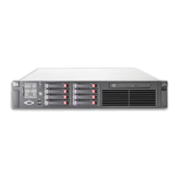
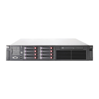
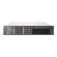
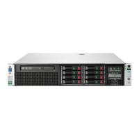
Diagrams and labels identifying all components on the server's front panel.
Description of front panel LEDs and buttons, including their status indicators.
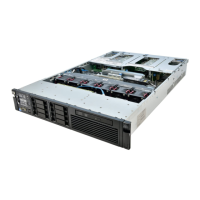
Diagrams and labels identifying all components on the server's rear panel.
Description of rear panel LEDs and buttons, including power supply and network activity indicators.
Detailed diagram of the system board with all connectors, sockets, and components labeled.
Explanation of system maintenance switch positions and their functions, including CMOS clearing.
Table explaining the status and function of diagnostic LEDs on the system board.
Describes NMI for generating crash dumps to aid in diagnosing system hangs and reliability issues.
Diagram showing the numbering of the 12 DIMM slots on the system board.
Details the status indicators for NICs, Power Cap, and AMP on the Systems Insight Display.
Explains how system LED combinations and the health LED indicate server status and events.
Illustrates SFF and LFF device bay numbering for hard drives.
Identifies the Fault/UID and Online LEDs on SAS and SATA hard drives.
Interprets combinations of Online/activity and Fault/UID LEDs for drive status.
Explains the status indicators for PCI riser cage LEDs related to AC power connection.
Defines slot types, form factors, and riser descriptions for non-hot-plug PCI slots.
Details the System Power, Auxiliary Power, Battery Health, and BBWC Status LEDs.
Explanation of Green and Amber LEDs on the FBWC module for backup and charging status.
Information on hot-plug fan installation and cautions for single-processor configurations.
Details operating, shipping, and storage temperature and humidity ranges.
Provides dimensions, weight, voltage, current, power, and BTU ratings for the server.
Details specifications for 460W, 750W, and 1200W power supplies, including input/output parameters.
Reference to HP Enterprise Configurator for power supply calculations and heat loading.
Technical details for the CD-ROM drive, including disk formats, capacity, and dimensions.
Technical details for the DVD-ROM drive, including disk formats, capacity, and dimensions.
Specifications for 36GB SAS, 72GB SAS, and 60GB SATA drives, including capacity and interface.
Glossary of common acronyms and abbreviations used in the document.
| Memory | Up to 512 GB DDR3 |
|---|---|
| Form Factor | 2U Rack |
| Processor | AMD Opteron 6100 Series |
| Storage | Up to 16 SFF SAS/SATA or 6 LFF SAS/SATA |
| Network | Embedded NC382i Dual Port Gigabit Server Adapter |
| Power Supply | Up to two hot-plug, redundant power supplies |
| Expansion Slots | Up to 6 PCIe Gen2 slots |
| RAID Support | HP Smart Array P410 |
| Network Controller | HP NC382i Dual Port Multifunction Gigabit Server Adapter |
| Management | HP Integrated Lights-Out (iLO 3) |