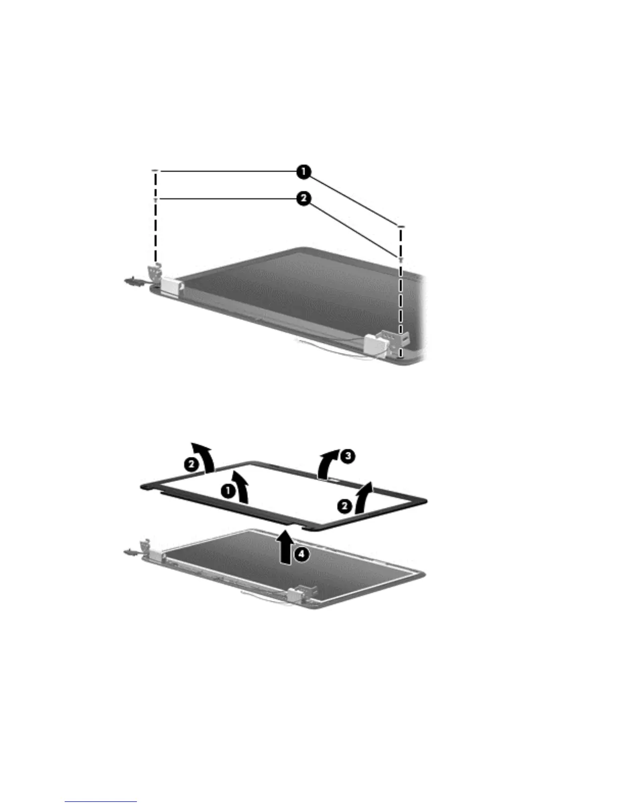
8. To replace any of the display assembly internal components, remove the following screw covers
and screws:
(1) Two mylar screw covers on the display bezel bottom edge
(2) Two Phillips PM2.5×4.0 screws
The display screw covers are included in the display rubber kit, spare part number 612106-001.
9. Flex the inside edge of the top (1), the left and right sides (2), and the bottom (3) of the display
bezel until the bezel disengages from the display back cover.
10. Remove the display bezel (4).
Reverse this procedure to install the display bezel.
11. To replace the webcam module (select models only), lift the webcam module as far from the
display enclosure as the webcam module cable allows.
70 Chapter 4 Removal and replacement procedures