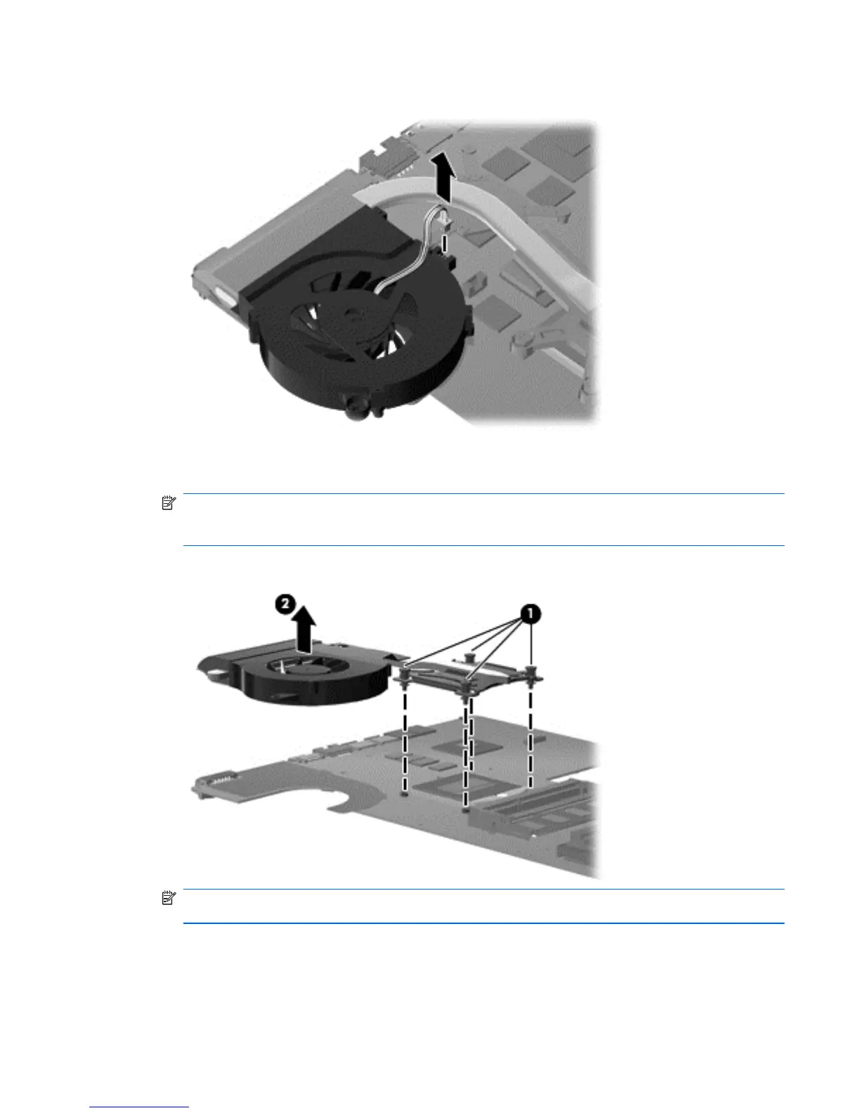
2. Disconnect the fan cable from the system board.
3. Follow the sequence embossed on heat sink to loosen the four Phillips PM2.5×7.0 captive
screws (1) that secure the fan/heat sink assembly to the system board.
NOTE: Due to the adhesive quality of the thermal material located between the fan/heat sink
assembly and system board components, it might be necessary to move the fan/heat sink
assembly from side to side to detach the assembly.
4. Remove the fan/heat sink assembly (2) by lifting straight up.
NOTE: Steps 5 through 8 apply only to computer models equipped with graphics subsystems
having discrete memory.
5. Turn the system board right-side up, with the front toward you.
Component replacement procedures 79