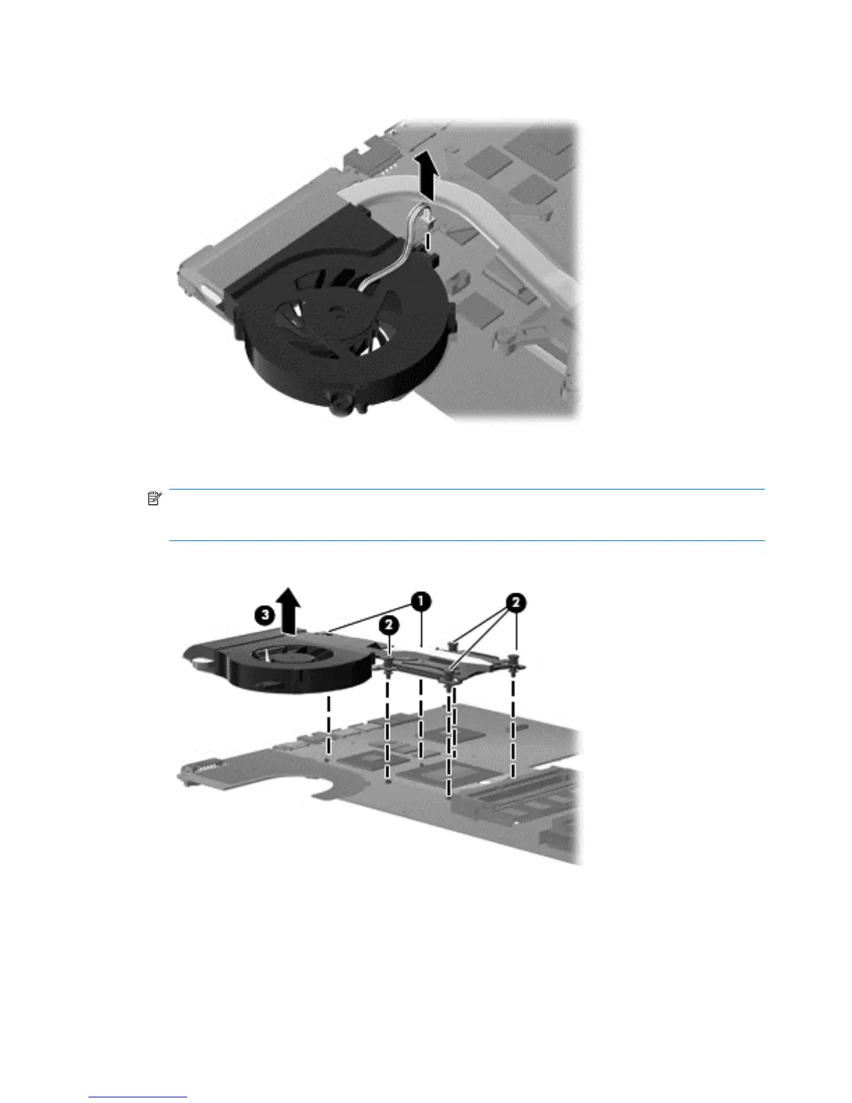
6. Disconnect the fan cable from the system board.
7. Loosen the two Phillips captive screws (1) and four Phillips spring-loaded captive screws (2) that
secure the fan/heat sink assembly.
NOTE: Due to the adhesive quality of the thermal material located between the fan/heat sink
assembly and system board components, it might be necessary to move the fan/heat sink
assembly from side to side to detach the assembly.
8. Remove the fan/heat sink assembly (3) by lifting straight up.
Reverse this procedure to install the fan/heat sink assembly.
The thermal material must be thoroughly cleaned from the surface of the fan/heat sink assembly (1),
(3) and the processor (2) and video components (4) each time the fan/heat sink assembly is
removed. Thermal pads and thermal paste must be installed on all surfaces before the fan/heat sink
assembly is reinstalled.
80 Chapter 4 Removal and replacement procedures