2-1
2
Installing the Switch
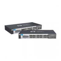
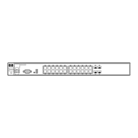
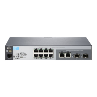
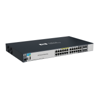
This chapter provides installation information for the V1410-8 Switch,
V1410-16 Switch, V1410-24 Switch, and V1410-24-2G Switch.
Included Parts
The switches have the following components:
■ Documentation kit
■ Four rubber feet
■ Wall/table-mount accessory kit:
■ Rack-mount accessory kit:
• Read Me First
• Switch Quick Setup Guide
• Safety and Regulatory information
• Software End User License and Hardware Warranty information
Kit number 5066-0621
Contains:
• three 3/4” (20-mm M4) screws for
wall and under-table mounting
• three wall anchors
• cable tie for power cord
V1410-16 Switch V1410-24 Switch
V1410-24-2G Switch
Kit number 5066-0622
Contains:
• two mounting brackets
• eight 8-mm M4 screws to attach the
mounting brackets to the switch
• four 5/8-inch number 12-24 screws to
attach the switch to a rack
Kit number 5066-0623
Contains:
• two mounting brackets
• eight 8-mm M4 screws to attach the
mounting brackets to the switch
• four 5/8-inch number 12-24 screws to
attach the switch to a rack