2-14
Installing the Switch
Installation Procedure
2.) Re-check the LEDs during self test. See “Self Test LED Behavior” on
page 2-8.
3. For the HP 1820 8-port switches, use the included cable tie to secure the
power cord to the switch.
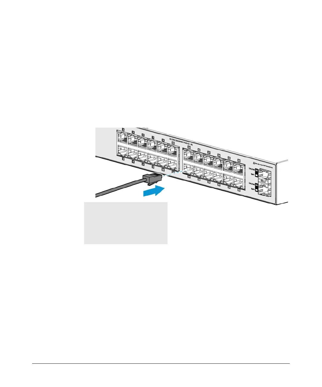
5. Connect the Network Cables
Connect the network cables, from the network devices or your patch panels,
to the fixed RJ-45 ports on the switch or to any SFP transceivers you have
installed in the switch.
When a network cable from an active network device is connected to the port,
the port LEDs for that port should go on. If the port LEDs do not go on when
the network cable is connected to the port, see “Diagnosing with the LEDs”
on page 4-2.
100-ohm unshielded or shielded twisted-
pair cable:
• Category 3, 4, or 5 for 10 Mbps ports
• Category 5 only for 100 Mbps ports
• Category 5, 5e, or 6 for 1000 Mbps ports
Maximum distance: 100 meters
 Loading...