Index-1
Numerics
10/100BASE-TX ports
location on switch … 1-2
1000Base-T
1000Base-T
fiber-optic cable specifications … A-5
A
acoustic specifications … A-2
auto MDI/MDI-X operation … A-9, A-11
HP Auto-MDIX feature … A-7
B
back of switch
power connector … 1-6
basic troubleshooting tips … 4-1
blinking LEDs
error indications … 4-2, 4-5
buttons
Reset button … 1-6
C
cabinet
mounting the switch in … 2-9, 2-11
cables
connecting cables to switch ports … 2-14–2-15
infrastructure requirements … 2-6
cables, twisted pair
category 3, 4, 5 … A-7
cross-over cable pin-out … A-10
MDI-X to MDI connections … A-9, A-11
MDI-X to MDI-X connections … A-10
pin-outs … A-9, A-11
straight-through cable pin-out … A-9, A-11
switch-to-computer connection … A-9, A-11
switch-to-switch or hub connection … A-10
cables, twisted-pair
HP Auto-MDIX feature … A-7
wiring rules … A-7
cables, twisted-pair connector pin-outs … A-7
cabling infrastructure … 2-6
Clear button
location on switch … 1-2
restoring factory default configuration … 1-6,
4-5
configuration
restoring factory defaults … 1-6
connecting the switch to a power source … 2-13
console port
location on switch … 1-2
cross-over cable
pin-out … A-10
D
description
front of switch … 1-2
LEDs … 1-5
switch … 1-1
E
electrical specifications, switch … A-1–A-2
environmental specifications, switch … A-2
F
factory default configuration, restoring … 1-6
Fault LED
location on switch … 1-2
showing error conditions … 4-2
fiber-optic cables
1000Base-T … A-5
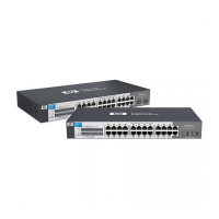
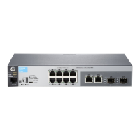
front of switch … 1-2
10/100BASE-TX ports … 1-2
description … 1-2
network ports … 1-4
Reset button … 1-6
H
horizontal surface
mounting switch on … 2-12
HP Auto-MDIX
feature description … A-7
Index
 Loading...