


O
odonnellangelaJul 29, 2025
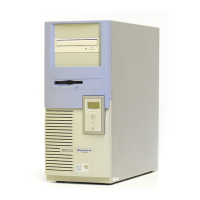
What to do if there is no video on my HP Kayak XU800?
- JJacob AllenJul 29, 2025
If your HP Desktop displays no video, verify that the video card is present and correctly seated in the AGP PRO connector. Ensure it's cabled correctly and is not defective.