●
WLAN module (see
WLAN module on page 46)
●
Memory module (see
Memory module on page 51)
●
RTC battery (see
RTC battery on page 53)
●
Fan/heat sink assembly (see
Fan/heat sink assembly on page 71)
Remove the system board:
1. Disconnect the display panel cable from the system board.
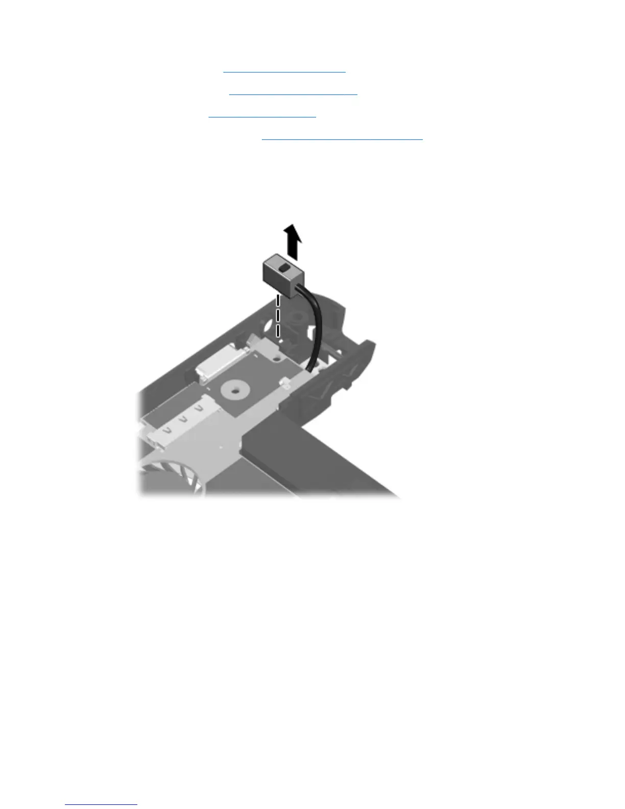
2. Disconnect the power connector cable from the system board.
3. Remove the Phillips PM2.0×4.0 screw (1) that secures the system board to the base enclosure.
4. Lift the right side of the system board (2) until it rests at an angle.
Component replacement procedures
69