11. Remove the cables from the clips built into the computer.
12. Remove the drive connector from the computer.
To install the hard drive connector, reverse the removal procedures.
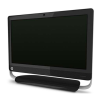
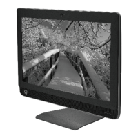
Front Bezel
Description Spare part number
Front bezel kit 704214-001
The front bezel is located on the front of the computer and secured with 6 screws and tabs on each
side. You must remove the power button assembly from the bezel to remove the bezel from the
computer.
To remove the front bezel:
1. Prepare the computer for disassembly (see
Preparing to Disassemble the Computer
on page 27).
2. Remove the small rear cover (see
Small Rear Cover on page 28).
3. Remove the stand (see
Stand on page 29).
4. Remove the right rear cover (see
Right Rear Cover on page 35).
5. Remove the heat sink (see
Heat Sink (Thermal Module) on page 38).
6. Remove the rear cover (see
Rear Cover on page 46).
7. Remove the system board shield (see
System Board Shield on page 51).
8. Remove the system board (see
System Board on page 56).
9. Remove the stand bracket (see
Stand Bracket on page 58).
60 Chapter 7 Removal and Replacement Procedures All-in One (AIO) Chassis
 Loading...