c. Switch cover and keyboard (see Switch cover and keyboard on page 76).
d. Display assembly (see
Display assembly on page 81).
e. Top cover (see
Top cover on page 91).
f. USB board (see
USB board on page 98).
g. System board (see
System board on page 101).
h. Fan/heat sink assembly (see
Fan/heat sink assembly on page 105).
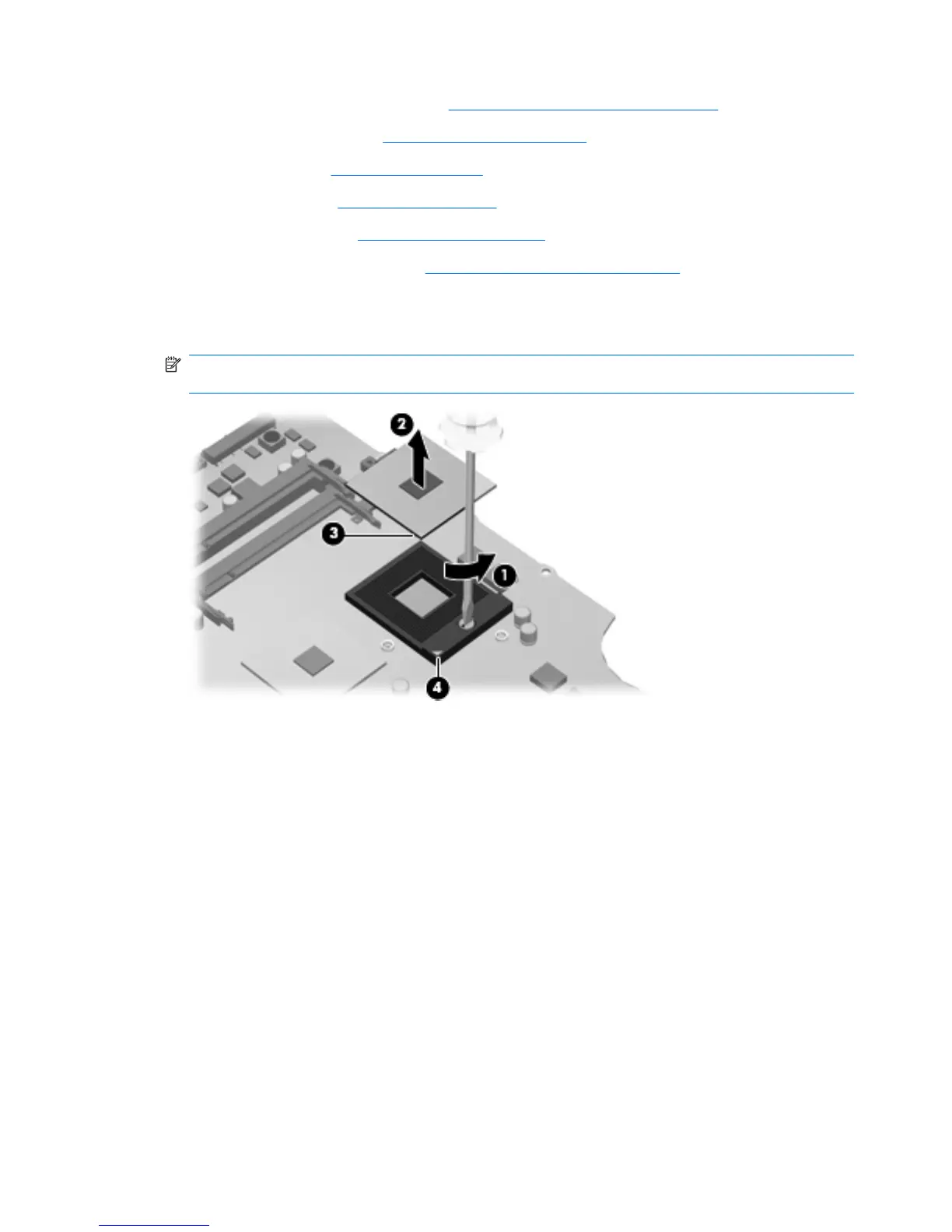
1. Turn the processor locking screw (1) one-half turn counterclockwise until you hear a click.
2. Lift the processor (2) straight up and remove it.
NOTE: The gold triangle (3) on the processor must be aligned with the triangle icon (4) embossed
on the processor socket when you install the processor.
Reverse this procedure to install the processor.
108 Chapter 4 Removal and replacement procedures
 Loading...