Before removing the I/O board, follow these steps:
1. Prepare the computer for disassembly (see Preparation for disassembly on page 37).
2. Remove the bottom cover (see Bottom cover on page 37).
3. Disconnect the battery cable from the system board (see Battery on page 46).
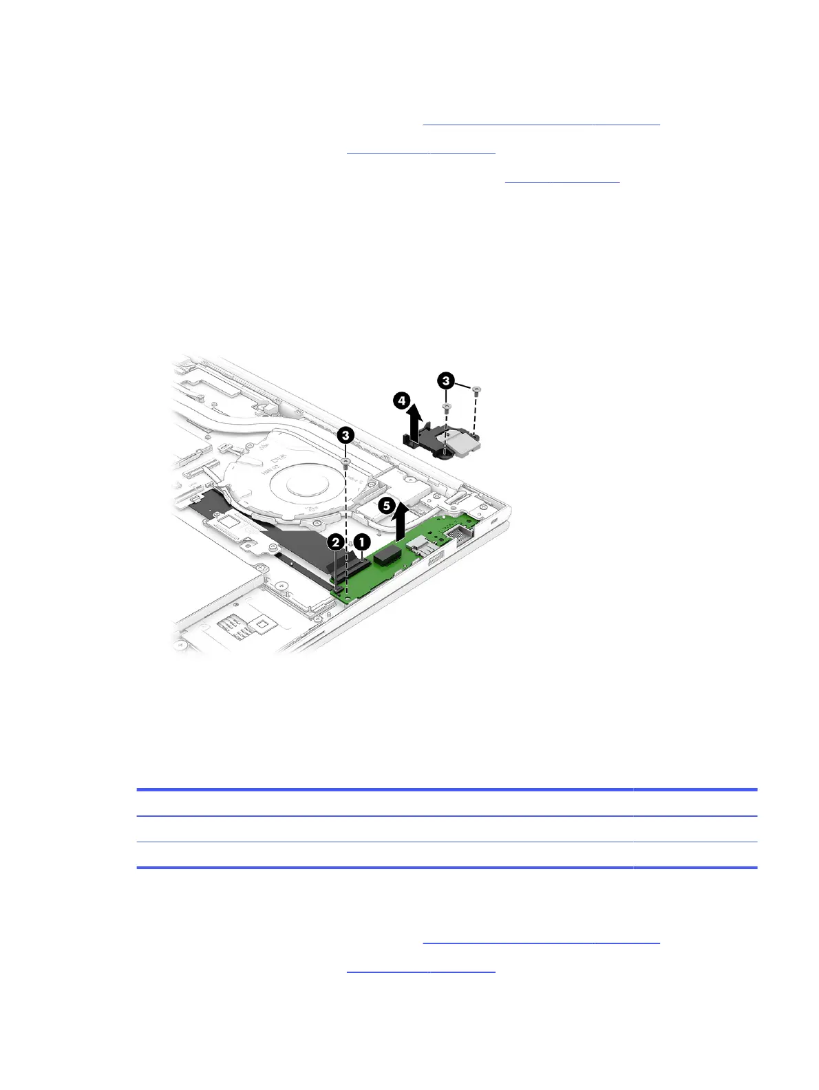
Remove the I/O board:
1. Disconnect the cables from the larger ZIF connector (1) and smaller ZIF connector (2) on the I/O
board.
2. Remove the three Phillips M2.0 × 4.0 screws (3) that secure the board to the computer, and then
remove the network jack door from the board (4).
3. Remove the board from the computer (5).
To install the I/O board, reverse this procedure.
Touchpad
To remove the touchpad, use this procedure and illustration.
Table 6-4
Touchpad description and part number
Description Spare part number
Touchpad N54002-001
Touchpad cable (included in Cable Kit) N03218-001
Before removing the touchpad, follow these steps:
1. Prepare the computer for disassembly (see Preparation for disassembly on page 37).
2. Remove the bottom cover (see Bottom cover on page 37).
Touchpad
49
 Loading...