1-6
Introducing the Switch
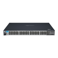
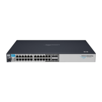
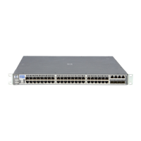
Front of the Switch
Introducing the Switch
Table 1-2. EPS/RPS LED Behavior
T/M
(green – ports
21 - 24 or 45-
48)
On For the dual-personality ports, indicates the enabled connector:
• if the “T” is on, the 10/100/1000Base-T RJ-45 connector is enabled.
• if the “M” is on, the mini-GBIC connector is enabled.
Fan Status
(green)
On Normal operation, all fans are ok.
Blinking* One of the unit’s fans has failed. The switch Fault LED will be blinking simultaneously.
RPS Status
(green)
On
Blinking
Off
Normal operation. An HP ProCurve EPS/RPS unit is connected and operating correctly.
The EPS/RPS could be powering the unit - see table below.
The EPS/RPS is connected but may be powering another switch or the EPS/RPS has
experienced a fault.
The EPS/RPS is not connected or is not powered.
* The blinking behavior is an on/off cycle once every 1.6 seconds, approximately.
Switch LEDs State Meaning
EPS/RPS
modes:
This table describes the behavior of the EPS/RPS and LEDs associated with EPS/RPS operation (Power,
EPS/RPS, Fault)
Power LEDs EPS/RPS
LED
Fault LED Description
On Off Off Normal operation. EPS/RPS is not connected or not powered
On On Off Normal operation. EPS/RPS is available.
On On/Off Blinking Unit has experienced a fault and another LED will be blinking to
determine fault.
Off On Blinking EPS/RPS is running unit in failover mode. No AC power to the unit, or
the internal power supply has failed
Off Off Off Unit is un-powerd by AC input line and the external EPS/RPS
On Blinking Blinking EPS/RPS unit has experienced a fault
On Blinking Off EPS/RPS unit is unavailable to power the unit in the event of an internal
power supply failure. The external EPS/RPS is designed to provide
power to one of its connected switch devices at a time. The Power
Status LED on the external EPS/RPS unit will also be blinking for this
device.
 Loading...