Component identification 11
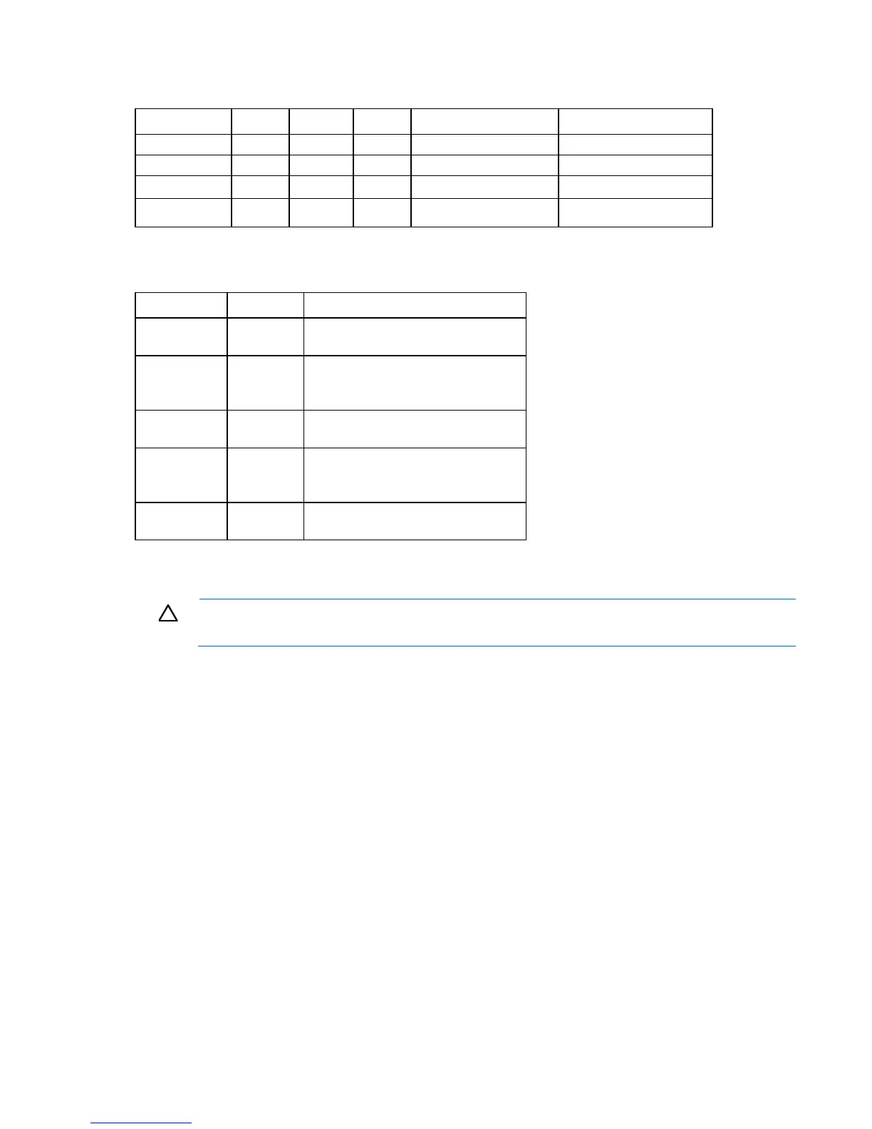
PCIe expansion slot definitions
Slot number Type Length Height Connector link width Negotiable link width
1
PCIe2 Half Full x4 x1signal / 25W
2
PCIe2 Half Full x8 x1 signal / 25W
3
PCIe3 Half Full x8 x8 signal / 25W
4
PCIe3 3/4 Full x16 x8 signal / 75W
System maintenance switch
Switch Default Function
1
Off Off = No function
On = iLO security is disabled
2
Off Off = System configuration can be
changed
On = System configuration is locked
5
Off Off = Power-on password is enabled
On = Power-on password is disabled
6
Off Off = No function
On = ROM reads configuration as
invalid
3, 4, 7, 8, 9,
10, 11, 12
— Reserved
When the system maintenance switch position 6 is set to the On position, the system is prepared to erase all
system configuration settings from both CMOS and NVRAM.
CAUTION: Clearing CMOS and/or NVRAM deletes configuration information. Be sure to
properly configure the server or data loss could occur.
NMI functionality
An NMI crash dump creates a crash dump log before resetting a system which is not responding.
Crash dump log analysis is an essential part of diagnosing reliability problems, such as failures of operating
systems, device drivers, and applications. Many crashes freeze a system, and the only available action for
administrators is to restart the system. Resetting the system erases any information which could support
problem analysis, but the NMI feature preserves that information by performing a memory dump before a
system reset.
To force the system to invoke the NMI handler and generate a crash dump log, do one of the following:
• Use the iLO Virtual NMI feature.
• Short the NMI header ("System board components" on page 9).
For more information, see the HP website (http://www.hp.com/support/NMI).
 Loading...