Hardware options installation 37
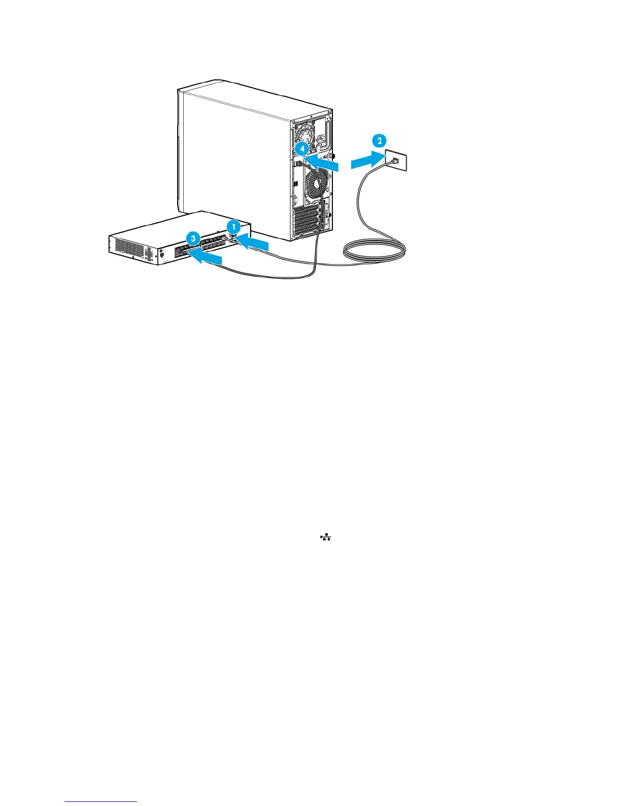
3. Connect the cable to any switch network port.
Completing the switch Self-Test
1. Connect the power adapter to the switch.
2. Connect the power adapter to the AC power source.
3. Check the status of the switch Power LED. This LED is solid green to indicate that the power connection
is established.
4. Check the status of the following switch LEDs:
o Link/Act LED on the switch network port that is being used—Initially, solid green to indicate
successful connection, and then flashing green to indicate active communication with the network.
o Fault LED—Remains off to indicate successful Self-Test completion.
For more information on the location of the switch LEDs and their behavior during the Self-Test process,
see the switch documentation.
Completing the switch setup
After the Ethernet cable connection is made, check the network LED status on both the server and the switch
to confirm successful connection:
• In the server front panel, the NIC status LED —Solid green
• In the switch, the Link/Act LED on the network connector used—Initially, solid green to indicate
successful connection, and then flashing green to indicate active communication with the network.
HP Trusted Platform Module option
For more information about product features, specifications, options, configurations, and compatibility, see
the product QuickSpecs on the HP website (http://www.hp.com/go/qs).
Use these instructions to install and enable a TPM on a supported server. This procedure includes three
sections:
1. Installing the Trusted Platform Module board.
2. Retaining the recovery key/password (on page 40).
 Loading...