4. Slide the system board (2) forward until the rear edge of the system board is clear of the keyboard/
top cover.
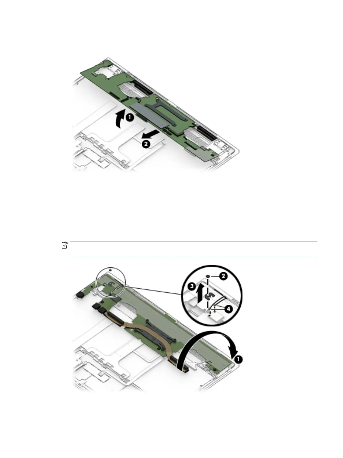
5. Swing the front edge of the system board (1) up and back until the system board rests upside down on the
keyboard/top cover.
6. Remove the Phillips M2.0×1.8 screw (2) that secures the WLAN module bracket to the system board.
7. Remove the WLAN module bracket (3).
The WLAN module bracket is available using spare part number L07401-001.
8. Disconnect the WLAN antenna cables (4) from the WLAN module built onto the system board.
NOTE: The #1/white WLAN antenna cable connects to the WLAN module "#1/Main" terminal. The #2/
black WLAN antenna cable connects to the WLAN module "#2/Aux" terminal.
9. Remove the system board.
Component replacement procedures 43