54 Troubleshooting
Resolving voltage and temperature warnings
1. Check that all of the fans are working by making sure each power supply’s DC Voltage/Fan
Fault/Service Required LED is off or by using SMU to check for yellow yield icon hardware warnings.
(In the Configuration View panel, right click the enclosure and click View > Overview.)
2. Make sure that all modules are fully seated in their slots and that their latches are locked.
3. Make sure that no slots are left open for more than two minutes.
If you need to replace a module, leave the old module in place until you have the replacement or use a
blank module to fill the slot. Leaving a slot open negatively affects the airflow and can cause the
enclosure to overheat.
4. Try replacing each power supply one at a time.
5. Replace the controller modules one at a time.
Sensor locations
The storage system monitors conditions at different points within each enclosure to alert you to problems.
Power, cooling fan, temperature, and voltage sensors are located at key points in the enclosure. In each
controller module and expansion module, the enclosure management processor (EMP) monitors the status
of these sensors to perform SCSI enclosure services (SES) functions.
The following sections describe each element and its sensors.
Power supply sensors
Each enclosure has two fully redundant power supplies with load-sharing capabilities. The power supply
sensors described in the following table monitor the voltage, current, temperature, and fans in each power
supply. If the power supply sensors report a voltage that is under or over the threshold, check the input
voltage.
Cooling fan sensors
Each power supply includes two fans. The normal range for fan speed is 4000 to 6000 RPM. When a
fan’s speed drops below 4000 RPM, the EMP considers it a failure and posts an alarm in the storage
system’s event log. The following table lists the description, location, and alarm condition for each fan. If
the fan speed remains under the 4000 RPM threshold, the internal enclosure temperature may continue to
rise. Replace the power supply reporting the fault.
During a shutdown, the cooling fans do not shut off. This allows the enclosure to continue cooling.
Temperature sensors
Extreme high and low temperatures can cause significant damage if they go unnoticed. Each controller
module has six temperature sensors. Of these, if the CPU or FPGA temperature reaches a shutdown value,
the controller module is automatically shut down. Each power supply has one temperature sensor.
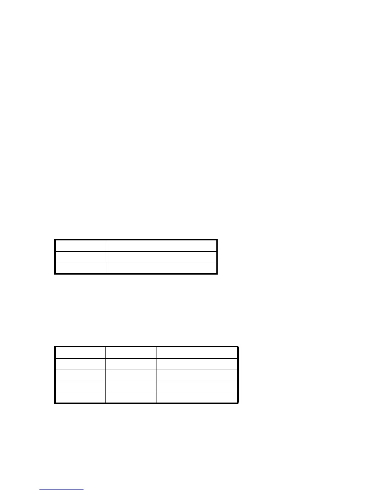
Table 8 Power supply sensors
Description Event/Fault ID LED condition
Power supply 1 Voltage, current, temperature, or fan fault
Power supply 2 Voltage, current, temperature, or fan fault
Table 9 Cooling fan sensor descriptions
Description Location Event/Fault ID LED condition
Fan 1 Power supply 1 < 4000 RPM
Fan 2 Power supply 1 < 4000 RPM
Fan 3 Power supply 2 < 4000 RPM
Fan 4 Power supply 2 < 4000 RPM