Do you have a question about the HP StorageWorks P2000 - G3 MSA Array Systems and is the answer not in the manual?
Specifies the target audience for this user guide.
Lists the knowledge and skills required before installation.
Provides a list of other HP documents relevant to the product.
Explains text formatting, symbols, and notation used in the manual.
Defines safety and caution symbols and their meanings.
Safety instructions for installing enclosures in racks to prevent tipping.
Contact information and procedures for obtaining HP technical support.
Details about HP's customer self-repair program for replacing parts.
Information regarding HP StorageWorks product warranty coverage.
How to sign up for HP product update notifications via email.
List of useful HP support and product-related websites.
Instructions on how to provide feedback on the user manual.
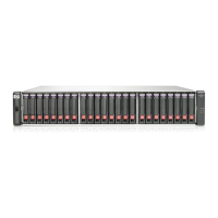
Highlights the key features and advantages of the HP StorageWorks P2000 G3 MSA System.
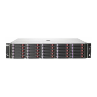
Identifies LEDs and ports on the front of LFF and SFF enclosures.
Diagrams showing disk drive bay numbering for LFF and SFF enclosures.
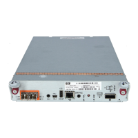
Overview of controller module rear panel connectors and ports.
Identifies rear panel components for FC SFF/LFF controllers.
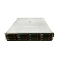
Diagram of the P2000 6Gb drive enclosure rear panel components.
Diagram of the MSA2000 drive enclosure rear panel.
Information on MSA70 drive enclosure compatibility with P2000 G3.
Information on D2700 drive enclosure compatibility with P2000 G3.
Explains write-back and read-ahead caching mechanisms.
How CompactFlash stores cache data during power loss.
Image and description of the controller module.
Procedure for preserving cache data on CompactFlash during controller failure.
Explains the super-capacitor's role in backing up cache during power failure.
Step-by-step guide for installing enclosures and initial system configuration.
General guidance on connecting controllers and various types of drive enclosures.
Important notes on SAS cables, connectors, and configuration limits.
Diagrams and tables detailing SAS cabling for P2000 G3 MSA System components.
Details SAS cable types, lengths, and connectors for controller-to-expansion connections.
Guidelines for mixing 3Gbps and 6Gbps drive enclosures for optimal performance.
Details SAS cable requirements between expansion modules.
Illustrates controller to drive enclosure cabling scenarios.
Illustrates controller to D2700 enclosure cabling scenarios.
Illustrates controller to MSA2000 enclosure cabling scenarios.
Illustrates controller to MSA70 enclosure cabling scenarios.
Shows fault-tolerant cabling for P2000 G3 controllers and P2000 6Gb drive enclosures.
Illustrates cabling scenarios for D2700 enclosures with P2000 G3 controllers.
Shows fault-tolerant cabling for MSA2000 3Gb drive enclosures.
Shows fault-tolerant cabling for MSA70 3Gb drive enclosures.
Illustrates mixed-connect cabling scenarios for dual controllers.
Procedures for testing enclosure connectivity and power sequencing.
Steps for powering the system on and off.
Detailed steps for powering on/off with switchless AC power supplies.
Identification of DC and legacy AC power supplies with power switches.
Instructions for connecting AC power cords to the system.
Instructions for connecting DC power cords to the system.
Steps for powering on and off the system.
Methods for obtaining network port IP addresses for the system.
Steps to configure IP addresses using a DHCP server.
Steps to configure IP addresses without a DHCP server.
Using the command line interface to set network port IP addresses.
Settings for configuring the terminal emulator display.
Settings for establishing a terminal emulator connection.
Command to restart the management controller on both controllers.
Requirements for host systems connecting to the P2000 G3 MSA System FC arrays.
General guidance on connecting hosts to storage enclosures.
Details about Fibre Channel host ports on the P2000 G3 MSA System FC controllers.
How to connect hosts directly to the controller's FC host ports.
Table of maximum cable lengths for 850nm Fibre Channel SFP transceivers.
Diagram showing a single controller connected to a single host path.
Diagrams illustrating dual controller configurations.
How to connect hosts via network switches.
Connecting hosts for out-of-band management over an Ethernet network.
Illustrates SAN replication setup between multiple servers and storage systems.
How to access the web-based Storage Management Utility (SMU).
Steps to configure and provision the storage system using SMU.
Steps to identify and isolate faults within the storage system.
How to collect essential information when a fault occurs.
Using enclosure LEDs and SMU to locate the source of a fault.
Importance of checking event logs for fault diagnosis.
Methods for isolating faults within data paths or components.
Troubleshooting steps for enclosures that fail to initialize.
How to correct enclosure ID mismatches after cabling.
Steps to diagnose faults by checking LED statuses.
Diagnosing issues based on disk drive module LED status.
Troubleshooting a disconnected host port link status LED.
Troubleshooting a disconnected expansion port link status LED.
Troubleshooting a disconnected network port link status LED.
Diagnosing issues with the power supply's AC Power Good LED.
Troubleshooting the drive enclosure's back panel OK LED.
Troubleshooting amber Fault/Service Required LED on drive enclosures.
Handling controller failure in single-controller setups.
Diagnosing controller boot issues using the Cache Status LED.
Procedure for moving cache data during controller replacement.
Steps to isolate faults in host-side connections.
Detailed troubleshooting for Fibre Channel host port connections.
Steps to isolate faults in controller module expansion port connections.
Actions for resolving voltage and temperature related warnings.
Overview of sensor locations within the storage system.
Details on power supply sensor monitoring for voltage, current, and temperature.
Information on cooling fan sensor monitoring and thresholds.
Details on temperature sensors within controller modules.
Information on temperature sensors within power supply modules.
Details on voltage sensors within power supply modules.
Description and definitions of front panel LEDs on enclosures.
Description of disk drive LEDs and their combinations.
Continued table of disk drive LED combinations and meanings.
Identifies and defines rear panel LEDs on controller modules.
Definition of the Cache Status LED.
Definition of the Expansion Port Status LED.
Identifies and defines rear panel LEDs for the 6Gb enclosure.
Identifies and defines rear panel LEDs for the MSA2000 enclosure.
Information on MSA70 drive enclosure compatibility with P2000 G3.
Information on D2700 drive enclosure compatibility with P2000 G3.
Explains power supply LEDs for AC and DC models.
General safety requirements for system installation and operation.
Guidelines for selecting a suitable installation site.
Requirements for AC power wiring, grounding, and connections.
Requirements for DC power wiring, grounding, and connections.
Guidelines for safely lifting and placing enclosures.
Guidelines for electrical connections, grounding, and safety.
Requirements for adequate airflow and cooling.
Guidelines for routing and managing cables to protect them from damage.
Requirements for connecting management hosts to the system.
Physical space and load requirements for installation.
Dimensions of the rackmount enclosures.
Weights of various enclosure configurations.
Specifications for altitude, humidity, temperature, shock, and vibration.
General electrical requirements and power cord specifications.
Precautions to prevent damage to system components from static electricity.
Methods for grounding oneself and equipment to prevent ESD.
| Drive Types Supported | SAS, SATA |
|---|---|
| RAID Levels | RAID 0, 1, 3, 5, 6, 10, 50 |
| Operating Temperature | 10°C to 35°C (50°F to 95°F) |
| Model | HP StorageWorks P2000 G3 MSA |
| Controller Types | Dual Controller |
| Host Interface | iSCSI, SAS, Fibre Channel |
| Form Factor | 2U |
| Number of Drive Bays | 24 |
| Power Supply | Dual, hot-plug, redundant power supplies |
| Cache Memory | 2 GB per controller |