Do you have a question about the HPE 1410-16G and is the answer not in the manual?
Verify the presence of the switch, accessory kit, power adapter, and documentation.
Review the 'Safety Precautions' on page 3 before proceeding with installation.
Connect the AC power adapter and confirm the switch's Power LED indicates 'On'.
Attach self-adhesive pads to the bottom corners for stable placement on a surface.
Use the included kit and M4 tap screws for secure wall or under-table installation.
Attach brackets using M4 screws and secure to rack with provided 12-24 screws.
Secure the switch physically using a Kensington lock or similar device (not included).
Power on the switch using the AC adapter and secure the connection with a cable tie strap.
Connect network cables to the switch ports for network connectivity.
Follow guidelines to prevent injury or product damage during installation.
Ensure proper grounding, use correct power cords, and avoid overloading circuits.
Ensure adequate airflow and do not exceed operating temperature specifications.
Details on AC input voltage, current, frequency, and power consumption.
Information on operating temperature and humidity ranges.
List of safety standards and laser classifications the product complies with.
Information on power adapter models and compatible power cords by region.
Official declaration of product compliance with EMC and Safety directives.
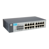
| Model | HPE 1410-16G |
|---|---|
| Layer | Layer 2 |
| Switching Capacity | 32 Gbps |
| Forwarding Rate | 23.8 Mpps |
| Jumbo frames | Up to 9216 bytes |
| Input voltage | 100-240 VAC |
| Ports | 16 |
| MAC address table size | 8000 entries |
| Operating Temperature | 0°C to 40°C |
| Operating Relative Humidity | 10% to 90% (noncondensing) |
| Dimensions | 440 x 180 x 44 mm |
| Mounting | Rack, wall, or desktop |
| Type | Unmanaged |