Do you have a question about the HPE FlexNetwork 5130 24G 4SFP+ 1-slot HI and is the answer not in the manual?
| Switching Capacity | 128 Gbps |
|---|---|
| VLANs Supported | 4094 |
| Manageable | Yes |
| Packet Buffer Memory | 4 MB |
| Model | HPE FlexNetwork 5130 24G 4SFP+ 1-slot HI |
| Ports | 24 x 10/100/1000 ports, 4 x 1/10G SFP+ ports |
| Power Supply | AC |
| MAC Address Table Size | 32K entries |
| Routing Protocol | Static, RIP, OSPF, BGP |
| Form Factor | 1U |
| Operating Temperature | 0°C to 45°C |
| Operating Humidity | 10% to 95% non-condensing |
Safety precautions to prevent equipment damage or injury during installation.
Requirements for selecting a suitable indoor installation location.
Maintain temperature and humidity for optimal equipment performance and longevity.
Dust buildup can cause electrostatic adsorption and communication failures.
Electromagnetic interference sources and prevention methods.
Warning about laser light from fiber ports potentially harming eyes.
Lists necessary tools for installation.
Lists and describes various installation accessories provided with the switch.
Procedures for mounting the switch in a standard 19-inch rack.
Details on available mounting bracket kits for different switch models.
Step-by-step guide for rack-mounting using front brackets.
Procedures for rack-mounting using both front and rear brackets.
Instructions for mounting the switch on a workbench.
Crucial steps for connecting the switch grounding cable for protection.
Detailed steps for grounding using a grounding strip.
Grounding method using a conductor buried in earth ground.
Procedures for installing and removing power supplies.
Step-by-step guide for installing specific PSR150 power supply models.
Steps to remove specific PSR150 power supply models.
Step-by-step guide for installing PSR720/PSR1110 power supply models.
Steps to remove PSR720/PSR1110 power supply models.
Instructions for connecting the power cord to the switch.
How to connect DC power supplies.
How to connect AC power supplies.
Procedures for installing and removing interface cards.
Step-by-step guide for installing an interface card.
Steps to remove an interface card.
Checks to perform after completing the switch installation.
Steps to prepare the PC for switch configuration.
Guide for connecting a console cable.
Guide for connecting a Mini USB console cable.
Required terminal settings for console connection.
Pre-checks and procedure for powering on the switch.
Visual flow of the IRF fabric setup process.
Key planning steps for setting up an IRF fabric.
Considerations for sizing and site selection of an IRF fabric.
How to select a master switch and plan member IDs.
Planning the network topology and connections for the IRF fabric.
Identifying physical IRF ports on member switches.
Guidelines for planning IRF fabric cabling.
Connecting switches within a single rack for IRF.
Connecting switches for a Top-of-Rack (ToR) solution.
Configuring member IDs, priorities, and port bindings.
Connecting the physical IRF ports between member switches.
Steps to verify the IRF fabric functionality.
Symptoms and solutions for power supply failure.
Symptoms and solutions for fan tray failure.
Procedures for removing a fan tray.
Procedures for installing a fan tray.
Troubleshooting display issues on the configuration terminal.
Steps to resolve when no display appears on the terminal.
Steps to resolve garbled text on the terminal display.
Diagrams showing the front and rear panels of the switch.
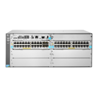
Front panel view of the HPE 5130 24G 4SFP+ 1-slot HI switch.
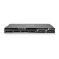
Front panel view of the PoE model.
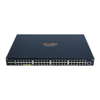
Front panel view of the 48-port model.
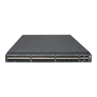
Front panel view of the 48-port PoE model.
Detailed technical specifications for non-PoE switch models.
Compatibility matrix for power supplies and interface cards.
Details on available hot-swappable power supplies and their specifications.
Details on available hot-swappable interface cards.
Details on various ports available on the switch.
Specifications for console ports.
Specifications for the management Ethernet port.
Information about the USB port.
Specifications for 10/100/1000Base-T Ethernet ports.
Details on SFP+ ports and compatible transceiver modules.
Overview of the switch's LEDs.
Description of the system status LED.
Description of power supply status LEDs.
Explanation of the MODE LED and its function.
Description of LEDs for 10/100/1000Base-T ports.
Description of SFP+ port LEDs.
Description of management Ethernet port LEDs.
Description of the interface card status LED.
Description of fan tray status LEDs.
Information on port status LEDs on interface cards.
Details on power supply input/output status LEDs.
Explanation of command and GUI conventions.
Icons used to represent network devices and connections.
How to access HPE support services and documentation.
How to find and download software updates.
List of relevant HPE networking and general websites.
Information about HPE's customer self-repair program.
Information on remote support services.
How to provide feedback on the documentation.


