CAUTION: To prevent improper cooling and thermal
damage, do not operate the enclosure unless all bays
are populated with a component or a blank.
1.
Install fans in even-numbered groups, based on the total
number of blades installed in the enclosure:
o Four-fan configuration—Fan bays 4, 5, 9, and 10 are used
to support a maximum of two devices located in device
bays 1, 2, 9, or 10. Only two device bays can be used with
four fans.
o Six-fan configuration—Fan bays 3, 4, 5, 8, 9, and 10 are
used to support devices in device bays 1, 2, 3, 4, 9, 10, 11,
or 12.
o Eight-fan configuration—Fan bays 1, 2, 4, 5, 6, 7, 9, and 10
are used to support devices in all device bays.
o Ten-fan configuration—All fan bays are used to support
devices in all device bays.
NOTE: When installing a fan in the top row of fan bays,
orient the fan so that the LED is in the lower right corner.
When installing a fan in the bottom row of fan bays,
orient the fan so the LED is in the upper left corner.
2.
Install fan blanks in any unused fan bays.
3.
Install the Onboard Administrator with KVM modules into the
Onboard Administrator with KVM tray based on the total
number ordered:
o One Onboard Administrator with KVM module: Bay 1
o Two Onboard Administrator with KVM modules: Bays
1
and 2
Install an Onboard Administrator with KVM blank into any
unused Onboard Administrator with KVM bay.
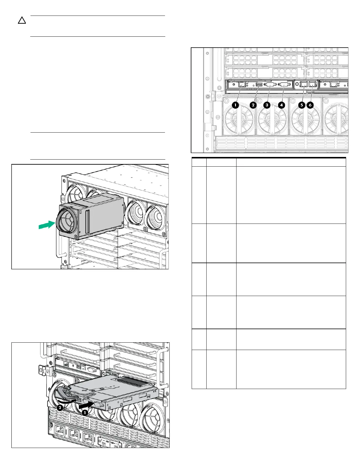
Connecting the cables
1.
Identify all connectors.
1 OA/iLO
Ethernet 1000BaseT RJ45 connector, which
provides Ethernet access to the Onboard
Administrator with KVM and the iLO on each
blade. Also supports interconnect modules
with management processors configured to
use the enclosure management network.
Autonegotiates 1000/100/10 or can be
configured to force 100Mb or 10Mb full
duplex.
2 USB USB 2.0 Type A connector used for
connecting supported USB devices such as
DVD drives, USB key drives, or a keyboard or
mouse for enclosure KVM use. To connect
multiple devices, a USB hub (not included) is
required.
3
Serial
connector
Serial RS232 DB-9 connector with PC
standard pinout. Connect a computer with a
null-modem serial cable to the Onboard
Administrator with KVM command line
interface (CLI).
connector
VGA DB-15 connector with PC standard
pinout. To access the KVM menu or Onboard
Administrator with KVM CLI, connect a VGA
monitor or rack KVM monitor for enclosure
KVM.
5
Enclosure
link-down
port
Connects to the enclosure link-up port on the
enclosure below with a CAT5 patch cable.
6 Enclosure
link-up port
and
service
port
Connects to the enclosure link-down port on
the enclosure above with a CAT5 patch cable.
On a stand-alone enclosure or the top
enclosure in a series of linked enclosures, the
top enclosure link-up port functions as a
service port.
2.
To connect to the management network, connect a standard
CAT5 patch cable to the OA/iLO port of each installed Onboard
Administrator with KVM module.
 Loading...