MF877-00 Page 2
Template Revision C, 30-July-2018
Copyright 2018 Hewlett Packard Enterprise Development LP
HPE instructions for this template are available at MF877-01
Quantity
of items
included
in product
Components, parts and materials containing
refractory ceramic fibers
Components, parts and materials containing
radioactive substances
List the type and size of the tools that would typically be used to disassemble the product to a point where components
and materials requiring selective treatment can be removed.
Tool Size (if
applicable)
3.0 Product Disassembly Process
3.1 List the basic steps that should typically be followed to remove components and materials requiring selective treatment:
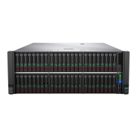
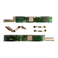
1. System Battery - Remove the top cover and locate the standup card in back pci card slot bay nex to the chassis wall.
Remove the board by pulling the front CPU drawer out ~ 3 inches then unscrewing the PCA's two blue finger screws
located on both ends of the PCA. Use a medium flat head screwdriver or fingers to remove the battery and dispose of
properly.
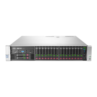
2. FBWC Battery - Some models, remove the battery from the holder and disconnect cable from PCA and dispose of
properly.
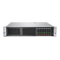
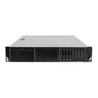
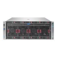
3. Capacitors=>2.5CM - Remove the power supplies from the system. With a #2 Philips screw driver, remove the screws
securing the top cover, then locate the capacitors and pry from the PCB with a medium flat head screw driver and
dispose of properly.
4.
5.
6.
7.
8.
3.2 Optional Graphic. If the disassembly process is complex, insert a graphic illustration below to identify the items
contained in the product that require selective treatment (with descriptions and arrows identifying locations).
Attachment 1 – System Battery location.
Attachment 2 – FBWC Battery.
Attachment 3,4, 5 - Capacitor location by model number of supply.
 Loading...