Do you have a question about the HPE ProLiant DL380 Gen9 and is the answer not in the manual?
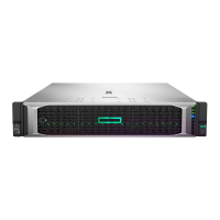
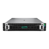
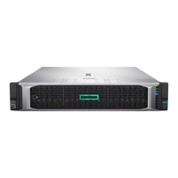
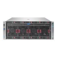
Visual aids detailing component locations for selective treatment, including batteries, mega cells, and capacitors.
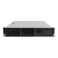
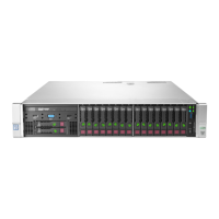
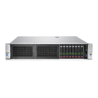
This document provides end-of-life disassembly instructions for Hewlett Packard Enterprise (HPE) ProLiant DL380 Gen9 servers, intended for recyclers and treatment facilities. Its primary function is to guide the removal of components and materials requiring selective treatment, as defined by the European Union's Waste Electrical and Electronic Equipment (WEEE) Directive 2012/19/EU.
The server is designed with several features that facilitate its maintenance and end-of-life processing. For instance, the access panel can be easily opened by releasing a retaining latch, allowing quick entry into the server's internal components. The air baffle, which helps manage airflow, is also designed for simple removal by pinching two locking latches. Similarly, the fan cage can be unlocked and lifted straight out of the chassis by rotating its handle, making fan replacement or cleaning straightforward. Individual fans within the cage can be pulled straight up from their finger grooves, simplifying their removal.
For more complex internal components, the design incorporates features for selective treatment. Printed Circuit Boards (PCBs) or Printed Circuit Assemblies (PCAs) with a surface area greater than 10 square centimeters are identified for specific handling. The server also contains batteries, including standard alkaline, lithium coin, or button style batteries, which are clearly marked for removal. Mercury-containing components, such as those found in lamps, display backlights, scanner lamps, switches, or certain battery types, are noted for special disposal, although in this specific model, the quantity is listed as zero. Liquid Crystal Displays (LCDs) with a surface greater than 100 square centimeters, including those with gas discharge lamps, are also identified, though none are present in this model. Cathode Ray Tubes (CRTs) and capacitors/condensers containing PCB/PCT are also listed as items requiring selective treatment, with none present in this model. However, electrolytic capacitors/condensers measuring greater than 2.5 cm in diameter or height are present and require specific handling, with their removal process detailed, often involving a Philips screwdriver to access and pry them from the PCB.
The disassembly process is structured to be methodical, starting with external access and moving inward. Expansion boards, if installed, are removed after loosening PCI riser cage thumbscrews and carefully lifting the cage. Cables, including serial port, mini SAS, power, and front cage cables, are disconnected at various stages to allow for the removal of associated components. The AROC card is secured by thumbscrews and can be carefully pulled out. DIMMs (Dual In-line Memory Modules) are removed by opening their slot latches. The heat sink, which is crucial for thermal management, is secured by four captive T-15 Torx screws and is removed using a cross-torque technique. Processors are accessed by opening their socket retaining bracket and locking levers. Power supplies are designed to be pulled out of their bays after pressing a release tab. FlexibleLOM (Flexible Local Area Network on Motherboard) options are carefully pulled away from the system board to disengage their connectors. Hard drive cages slide out from the front of the server. The mega cell cable is disconnected, and the mega cell itself is lifted out. The hard-drive backplane is secured by screws and is also removed. Finally, the system board itself is removed after loosening a thumbscrew and sliding it toward the front of the server.
The tools required for disassembly are minimal, primarily consisting of Torx drivers of sizes T15 and T10, which are commonly available. This simplifies the process for recyclers, as specialized tools are not extensively needed. The document also includes optional graphic illustrations to identify the locations of items requiring selective treatment, such as the system battery, mega cell, and capacitors within different power supply models (HSTNS-PD40, HSTNS-PL40, HSTNS-PC40, HSTNS-PD41, HSTNS-PL41, HSTNS-PD43). These visual aids enhance the clarity of the instructions, ensuring that components are correctly identified and removed. The detailed step-by-step instructions, combined with visual guidance, make the server's end-of-life processing efficient and compliant with environmental regulations.
| Processor Sockets | 2 |
|---|---|
| Memory Slots | 24 DIMM slots |
| Expansion Slots | Up to 6 PCIe 3.0 slots |
| Form Factor | 2U Rack |
| Processor | Intel Xeon E5-2600 v3/v4 |
| Memory | DDR4 SmartMemory |
| Storage | SAS, SATA, SSD options |
| Drive Bays | 25 SFF SAS/SATA/SSD |
| Network | 4 x 1GbE |
| Power Supply | 500W, 800W |
| Operating System Support | Windows Server, Linux, VMware |