HSD
5801H0056 _______________________________________________________________ 75/181
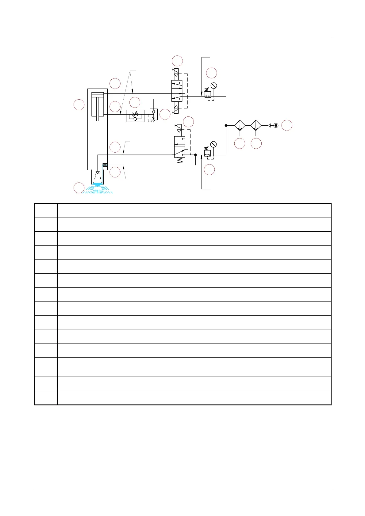
Example layout for the pneumatic circuit (arranged by the customer)
O8x6
6
4
3 2
1
10
8
5
4
9
14
12
13
O4x2
7
1
2
3
6Bar
4 Bar
O8x6
11
1.
Mains power supply.
2.
Pre-filter 5 µm.
3.
De-oiling filter 0.1 µm.
4.
Pressure regulator.
5.
Monostable valve 5-2, with electro-pneumatic command and spring return
6.
Air inlet for tool-holder release.
7.
Quick bleeder valve.
8.
One-way flow regulator, to adjust ejection speed.
9.
Air inlet for tool-holder hook-up.
10.
Double-acting pneumatic cylinder of the electrospindle.
11.
Monostable valve 3-1, with electro-pneumatic command and spring return
12.
Air inlet for cone cleaning (in all versions)
and for air jet via the tool (optional).
13.
Air inlet for pressurisation
14.
Continuous flow of pressurisation air.