HSD
5801H0056 _______________________________________________________________ 77/181
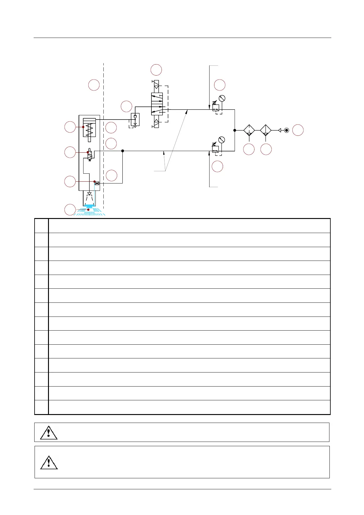
Example layout for the pneumatic circuit arranged by the customer
6
4
3 2
1
8
5
4
6 Bar
4 Bar
O
8x6
7
10
11
12
13
14
9
1
Mains power supply.
2
Pre-filter 5 µm.
3
De-oiling filter 0.1 µm.
4
Pressure regulator.
5
Pair of 3-way monostable electric valves, normally closed.
6
Quick bleeder valve.
7
Air input for tool-holder release.
8
Air inlet for cone cleaning
9
Air inlet for pressurisation
10
Pneumatic circuit inside the electrospindle.
11
Single acting pneumatic cylinder.
12
Valve to activate the cone cleaning (piston-commanded).
13
Throat.
14
Continuous flow of pressurisation air.
Use two separate circuits to connect the electric valves to the numerical control.
The use of two electric valves in series instead of just one reduces the possibility of
malfunctioning. Although such malfunctioning is very rare, the seriousness sometimes
means the application of the redundancy principle.