NEPTUNE
EN - 21
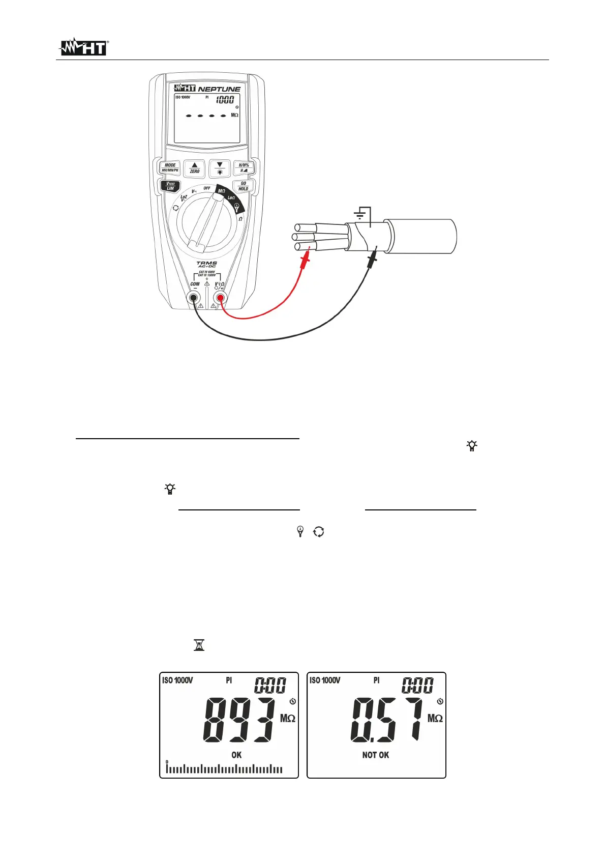
Fig. 22: Use of the instrument for insulation resistance measurement in PI mode
1. Select position M
2. Press key MODE/MXMNPK and select option “PI”
3. Press key VTEST/LIM to set the test voltage choosing among the values: 50V, 100V,
250V, 500V, 1000VDC. Please note the value in the top part of the display.
4. Press and hold key VTEST/LIM (>2s) to set the minimum limit threshold for
measurement. The symbol “Set” flashes on the display. Press keys / or /ZERO
to select the value among the options: 0.10M, 0.230M, 0.50M, 1.00M, 100M,
no. Option “no” indicates that no threshold was set (see Fig. 16).
5. Press keys / or /ZERO to select the measuring time (timer) choosing among
the options: 1min (for DAR measurement) or 10min (for PI measurement). Please note
the value in the top part of the display on the right (see Fig. 20).
6. Insert the red lead into input terminal V
/+ and the black lead into input terminal
COM/
and possible alligator clips, and connect the instrument to the appliance to be
tested (see Fig. 22).
7. Press key GO/HOLD to activate the test. The screen in Fig. 17 may appear on the
display to signal the presence of a voltage >10V found on the input terminals,
preventing the test to be carried out.
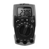
8. In case no anomalous conditions are found, the instrument performs the test in a
continuous mode with a countdown of time (until time “0:00”) for the entire duration of
the set timer, symbol flashes on the display and the buzzer gives out an intermittent
sound. At the end of the test, the following screens appear on the display.
Fig. 23: Results of insulation measurement in PI mode