NEPTUNE
EN - 26
6. If necessary, compensate the test cables (see § 5.7.1).
7. Insert the red lead into input terminal V /+ and the black lead into input terminal
COM/, and connect the instrument to the system to be tested (see Fig. 29).
8. Press key GO/HOLD to activate the test. The screen in Fig. 27 may appear on the
display to signal the presence of a voltage >10V found on the input terminals,
preventing the test to be carried out.
9. In case no anomalous conditions are found, the instrument performs the test in a
continuous mode with a countdown of time (until time “0”) for the entire duration of the
set timer, and symbol flashes on the display. At the end of the test, the following
screens appear on the display:
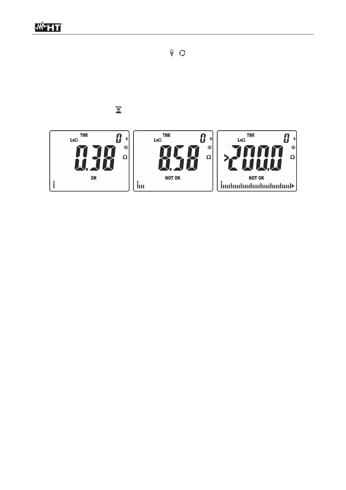
Fig. 31: Results of continuity test in TMR mode
10. In the screen in Fig. 31 – left side, a positive test result “OK” is shown (value lower than
the set threshold and test current >200mA). In the screen in Fig. 31 – middle, a
negative test result “NOT OK” is shown (value higher than the set threshold and test
current <200mA). In the screen in Fig. 31 – right side, a negative test result “NOT OK” is
shown, corresponding to the out-of-range condition (symbol “>200.0”).