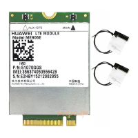
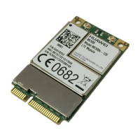
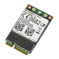
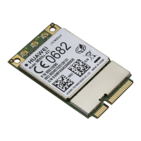
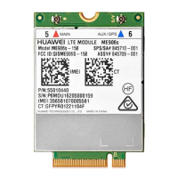
HUAWEI MU609 HSPA LGA Module
Hardware Guide
Description of the Application Interfaces
Huawei Proprietary and Confidential
Copyright © Huawei Technologies Co., Ltd.
It is recommended that route out the JTAG pins on the DTE board as the test point for
debugging.
3.10 RF Antenna Interface
The MU609 module provided three antenna pads (MAIN_ANT, GPS_ANT and
AUX_ANT) for connecting the external antennas.
Table 3-13 Definition of the antenna pads
Route the antenna pad as close as possible to antenna connector. In addition, the
impedance of RF signal traces must be 50 Ω.
Figure 3-15 RF signal trace design about MAIN_ANT for reference (the same for AUX &
GPS)

 Loading...


