HUAWEI MU736 HSPA+ M.2 Module
Hardware Guide
Description of the Application Interfaces
Huawei Proprietary and Confidential
Copyright © Huawei Technologies Co., Ltd.
The GPIO0~7 pins have configurable assignments. There are 4 possible functional
pin out configurations. These 4 configurations are called Port Config0~3. In each Port
Configuration each GPIO is defined as a specific functional pin. The GPIO pin
assignment can see in Table 3-14 . MU736 supports Config0. But the audio function is
not implemented in MU736.
Table 3-14 GPIO Pin Function Assignment per Port Configuration
Port Config0 (GNSS+Audio ver1)
3.9 NC Pins
The module has some NC pins. All of NC pins are not connected in the module.
Table 3-15 List of NC pins
28, 29, 31, 35, 37, 38,
41, 43, 47, 49, 50, 52,
53, 54, 55, 56, 58, 68
3.10 RF Antenna Interface
3.10.1 RF Connector location
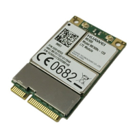
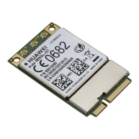
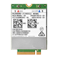
MU736 module provides 2 antenna connectors for connecting the external antennas.




 To Next Page