42
Check the fuse capacities of power supply devices.
Measure the voltage between NEG (-) and RTN (+) on the DC power distribution box.
Voltage Range If -48 V Power Is
Used
If -60 V Power Is
Used
-40 V to -57.6 V -48 V to -72 V
Do not power on the equipment if the power supply voltage does not meet the requirement.
Checking Fiber Attenuation
Wear protective glasses or goggles when you look directly at optical ports to check fiber attenuation.
2
2
1
1
Optical power
meter
Stable light
source
Optical power
P1
Short fiber
Optical power
P2
Fiber to be checked
External fiber
ODF
Measure the output power of the
optical source.
Measure the output power after the signal
traverses the fiber to be checked.
If the difference between P2 and P1 is less than 1 dB, the fiber connection is normal. If the difference is larger than
1 dB, clean the fiber. If the difference is still larger than 1 dB after cleaning, replace the fiber.
Setting the wavelength of the light source to approximately 1550 nm and the wavelength range of the optical power
meter to 1550 nm is recommended. After the equipment is powered on, you can also use a board that can
generate optical signals as a light source.
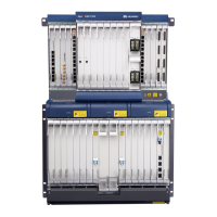
Subrack Type Maximum Power
Consumption
Fuse Capacity
OSN 9560 4800 W 60 A
OSN 3500
720 W (standard subrack) 20 A
1100 W (enhanced subrack) 32 A
OSN 7500 1100 W 32 A
CAUTION
CAUTION
NOTE
NOTE
 Loading...