EML-L29V100R001 Advanced Maintenance Manual V2.1
2 Working Principles and Materials
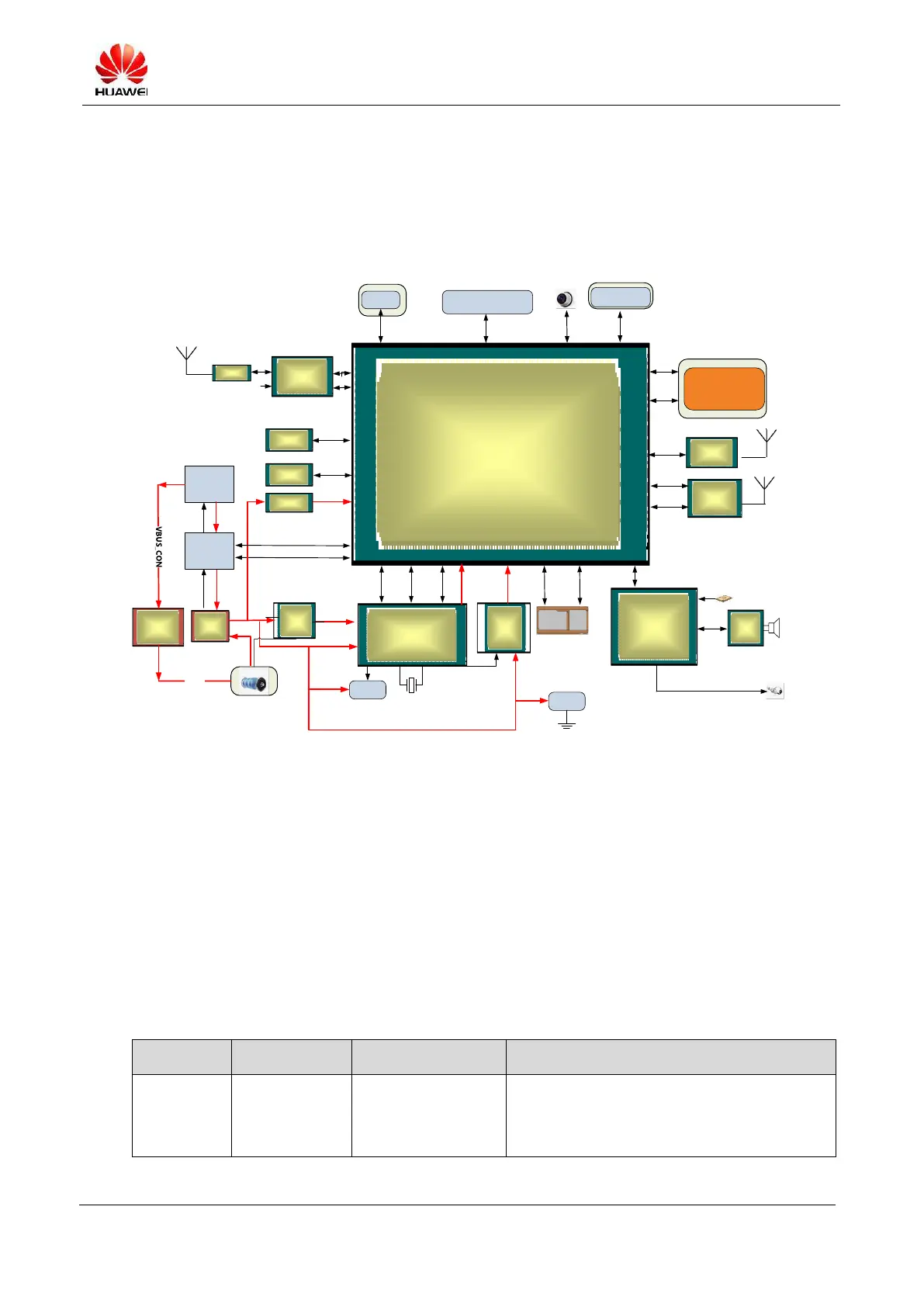
2.1 Block Diagram
Figure 2-1 Phone system block diagram
Fingerprint
sensor
Gravity sensor, ambient
light sensor, compass, hall
sensor, and gyroscope
Front camera
Rear
camera+flash
4lane MIPI
SPI2
I2C
SPI3
CSI1
DDR
UFS
PCIE
UART4
I2S
Mic x 2
I2S
SIM1
SIM0
SIM SIMSSI CLK CLK
SSI
38.4 MHz
32 kHz
RGB LED
Bluetooth
/Wi-Fi
SSI
IQ
38.4 MHz
Type-C USB
USB 3.0
USB OTG
VBUS
BQ25892
charger IC
(U1603)
U1201
Buckboost
(U1201)
HI6403
Codec
(U2201)
Smart PA
(U2501)
HI6421
PMU
(U1000)
HI6363
transceiver
X 2
(U3301&U4501)
RF: FEM
Wi-Fi
Bluetooth
HI3670 SOC
(U300)
For displaying
charging status
and notification
4Lane Dual
MIPI
CSI0&2
TP/LCD
DSI0
38.4 MHz
Vibrator
HI6422
PMU
(U1301)
38.4
MHz
DCDC
DCDC+LDO
LPDDR4X
U300_POP
DCDC
BCM435 96
(U5100)
Hi6423
U1101
UFS2.1
U1400
GPS
BCM477 4
U5603
GPS
UART3
Direct
charging
load switch
U1801
VBAT
SuperSwitch
USB 2.0
VBUS_CONUSB OTG
VBAT_SYS
The entire system is composed of the board, built-in battery, and mechanical parts. The board incorporates
the printed circuit board assembly (PCBA), side button FPC, main FPC, proximity sensor sub-board,
antenna sub-board, and other components such as the LCD module, camera module, motor, microphone,
speaker, and receiver. Mechanical parts include the middle cover, rear cover, main antenna,
GPS/Wi-Fi/Bluetooth antenna, and GSM antenna for the secondary SIM card.
2.2 Module Functions
Based on the logical functions, the board can be divided into four subsystems: baseband, RF, power supply,
and user ports. The following table describes the modules and units subordinated to each subsystem and
their functions.
Octa-core processor, with support for function
modules, such as SD 3.0, UART, SPI, SDIO,
I2C, I2S, PCM, HSI, HSIC, MIPI, DVP, GPIO,
HDMI, USB, keypad, LPDDR4 controller,

 Loading...