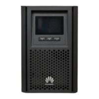
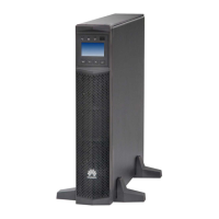
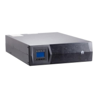
1. Connect the ground cable, as shown in the figure.
A ground terminal is typically marked
as .
The actual number of cables to be
connected and the positions vary
depending on the project design.
(Optional) Circuit breaker input
2. Connect the input power cables, as shown
in the figure.
3. Install the UPS input power cable.
1. The UPS input power cable wiring
diagram on the right is for reference
only. The number of cables to be
connected and the connection
positions vary depending on the
project design.
2. The UPS input may include an active
input and bypass input. For details
about the wiring port definitions and
wiring methods, see the Schematic
Diagram delivered with the PDU and
the UPS user manual.
(Optional) Wiring for a UPS Installed Inside a Cabinet
The wiring diagram is for reference only. The onsite conditions prevail. For details, see the
Schematic Diagram.
10
(1) Cables (connected
to the UPS input)
(2) UPS module
installation position

 Loading...


