Operation Manual - STP
Quidway S3000 Series Ethernet Switches Chapter 1 RSTP Configuration
1-3
Switch A
with priority 0
Switch C
with priority 2
Switch B
with priority 1
CP2
BP2
CP1
BP1
AP2
AP1
4
10
5
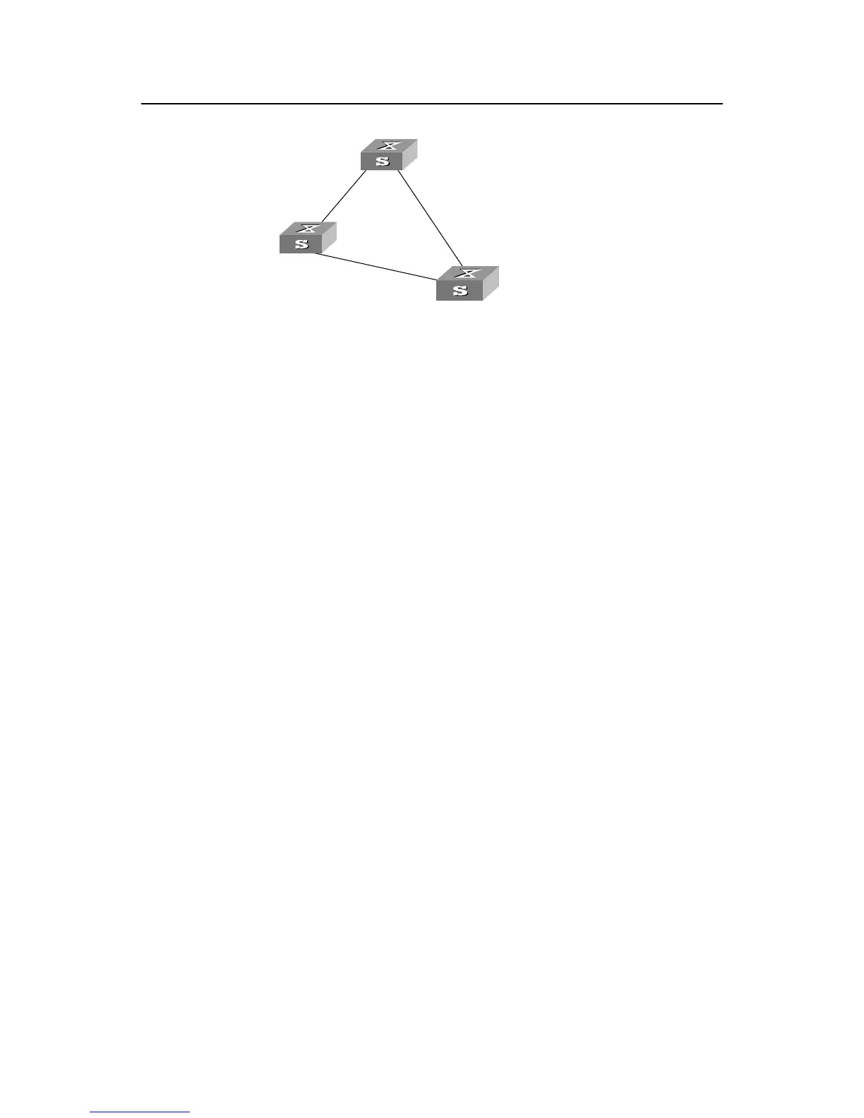
Figure1-2 Ethernet switch networking
To facilitate the descriptions, only the first four parts of the configuration BPDU are
described in the example. They are root ID (expressed as Ethernet switch priority), path
cost to the root, designated switch ID (expressed as Ethernet switch priority) and the
designated port ID (expressed as the port number). As illustrated in the figure above,
the priorities of Switch A, B and C are 0, 1 and 2 and the path costs of their links are 5,
10 and 4 respectively.
9) Initial state
When initialized, each port of the switches will generate the configuration BPDU taking
itself as the root with a root path cost as 0, designated switch IDs as their own switch
IDs and the designated ports as their ports.
Switch A:
Configuration BPDU of AP1: {0, 0, 0, AP1}
Configuration BPDU of AP2: {0, 0, 0, AP2}
Switch B:
Configuration BPDU of BP1: {1, 0, 1, BP1}
Configuration BPDU of BP2: {1, 0, 1, BP2}
Switch C:
Configuration BPDU of CP2: {2, 0, 2, CP2}
Configuration BPDU of CP1: {2, 0, 2, CP1}
10) Select the optimum configuration BPDU
Every switch transmits its configuration BPDU to others. When a port receives a
configuration BPDU with a lower priority than that of its own, it will discard the message
and keep the local BPDU unchanged. When a higher-priority configuration BPDU is
 Loading...