Do you have a question about the Huawei Quidway S3000-EI Series and is the answer not in the manual?
Configuration of Ethernet ports, including setup, enable/disable, and description settings.
Configuration and management of Virtual Local Area Networks (VLANs) for network segmentation.
Configuration and management of multicast protocols and services for efficient data distribution.
Quality of Service and Access Control List configuration for network traffic management and security.
Configuration and management of integrated system features for overall network control.
Spanning Tree Protocol configuration for preventing network loops and ensuring loop-free topology.
Configuration of security features to protect the network from unauthorized access and threats.
Configuration and management of various network protocols for optimal network operation.
Configuration and management of system-level settings for device operation and maintenance.
Configuration and management of remote power feeding capabilities, including PoE settings.
Supplementary information and reference materials for the manual.
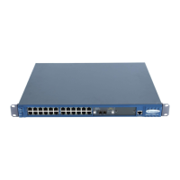
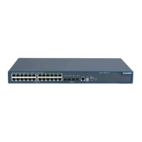
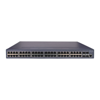
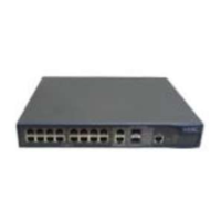
General introduction to the Quidway S3000-EI Series Ethernet Switches and their types.
Detailed description of the functional capabilities and features supported by the switches.
Steps to set up the local configuration environment using the console port for switch access.
Procedure for setting up remote configuration access using Telnet for switch management.
Instructions for connecting a PC to the switch via Telnet for configuration.
Configuration steps for accessing a switch via Telnet through another switch in the network.
Procedure for setting up remote configuration using a dial-up modem connection.
Overview of the command line interface features and characteristics for switch management.
Explanation of different command line views and their hierarchical protection mechanisms.
Detailed description of the features and functions available in the command line interface.
Information on how to access and use the online help features within the command line interface.
Details on how the command line interface displays information and handles command input.
Explanation of how to retrieve and use previous commands entered in the command line interface.
List of common error messages encountered in the command line interface and their causes.
Information on editing commands, cursor movement, and other text editing features in the CLI.
Overview of the different user interfaces for configuring and managing switch ports and data.
Detailed configuration steps for user interfaces, including entering views and setting protocols.
Instructions on how to enter specific user interface views for configuration tasks.
Configuration of supported protocols (Telnet, SSH) for user interface access.
Configuration of AUX (Console) port attributes like speed, flow control, parity, and data bits.
Configuration of terminal attributes such as screen length, idle timeout, and locking.
Setting the idle timeout for user sessions to automatically disconnect inactive users.
Configuring the screen length for displaying information in the terminal interface.
Setting the size of the command history buffer for recalling previous commands.
Management of user accounts, including authentication methods and access levels.
Configuration of authentication methods (password, scheme, none) for user access.
Setting the command level accessible to a user after logging into the system.
Setting the command level for users accessing the switch via specific user interfaces.
Setting the priority of commands within specific views to manage access authorities.
Configuration of packet redirection to specific destinations based on QoS policies.
Sending messages between different user interfaces for inter-user communication.
Configuring commands to automatically execute upon user login for automation.
Overview of system IP configuration, including management VLAN and IP address structure.
Configuration and importance of the management VLAN for switch IP configuration.
Explanation of IP address classification, structure, and common formats.
Details on IP address classes (A, B, C, D, E) and their respective ranges and uses.
Explanation of subnetting and masks for IP address allocation and network division.
Configuration of static routes for manual network path definition and traffic control.
Comprehensive system IP configuration including VLANs, hostnames, and static routes.
Steps to create or delete a management VLAN interface for IP configuration.
Assigning or deleting IP addresses for the management VLAN interface.
Setting or deleting a descriptive character string for the management VLAN interface.
Enabling or disabling the management VLAN interface to control its operational status.
Configuring the hostname and associating it with the host IP address for easier network identification.
Configuration of static routes to define specific paths for network traffic.
Setting the default preference value for static routes when no specific preference is defined.
Commands for displaying and debugging system IP configuration to verify settings.
Overview of Ethernet ports on Quidway S3000-EI Series switches, including types and features.
Detailed configuration steps for Ethernet ports, including entering views and enabling/disabling.
Instructions on how to enter the Ethernet port view for configuration tasks.
Enabling or disabling Ethernet ports to control their operational status and data forwarding.
Setting a descriptive character string for Ethernet ports to distinguish them.
Configuration of duplex attributes (auto, full, half) for Ethernet ports to manage data transmission.
Setting the operational speed of Ethernet ports, including auto-negotiation and specific speeds.
Configuration of the cable type (straight-through, cross-over) connected to Ethernet ports.
Enabling or disabling flow control on Ethernet ports to manage network congestion.
Setting the ratio for broadcast suppression on Ethernet ports to manage broadcast storms.
Configuration of link types (access, hybrid, trunk) for Ethernet ports.
Adding Ethernet ports to specified VLANs for network segmentation and traffic control.
Setting the default VLAN ID for access ports, hybrid, and trunk ports.
Configuration of loopback detection on Ethernet ports for fault diagnosis.
Setting the time interval for calculating port statistics, such as average port speed.
Configuring traffic thresholds on ports to prevent network blocking due to high traffic.
Commands for displaying and debugging Ethernet port configurations and status.
A practical example demonstrating the configuration of Ethernet ports and related features.
The networking scenario and requirements for the Ethernet port configuration example.
Overview of link aggregation, explaining its purpose for enhancing reliability and load balancing.
Steps and commands for configuring link aggregation groups to combine multiple ports.
Instructions on aggregating Ethernet ports to form link aggregation groups.
Introduction to Virtual Local Area Networks (VLANs), their purpose, and benefits.
Steps and commands for configuring VLANs, including enabling, creating, and managing ports.
Enabling or disabling the VLAN feature on the switch for network segmentation control.
Procedures for creating new VLANs or deleting existing VLANs from the switch configuration.
Assigning Ethernet ports to specific VLANs to control network traffic flow and segmentation.
Setting or deleting a descriptive string for VLANs to aid in identification and management.
Commands for displaying and debugging VLAN configurations and status.
A practical example demonstrating the configuration of VLANs and port assignments.
Introduction to isolate-user-vlan, a feature for saving VLAN resources and implementing Layer-2 packet isolation.
Steps and commands for configuring isolate-user-vlan, including creating VLANs and mapping ports.
Detailed instructions for creating and configuring an isolate-user-vlan.
Configuration of secondary VLANs that can be mapped to isolate-user-vlans.
Mapping isolate-user-vlans to secondary VLANs for implementing Layer-2 packet intercommunication.
Configuration of VLAN ID for IGMP packets to ensure proper multicast traffic handling.
Commands for displaying and debugging isolate-user-vlan configurations.
Configuration of the Generic Attribute Registration Protocol (GARP) for distributing and registering network information.
Introduction to GARP, its role in registration protocols, and its applications like GVRP and GMRP.
Configuration of GARP timers (Hold, Join, Leave, LeaveAll) for controlling protocol behavior.
Commands for displaying GARP statistics and debugging GARP configurations.
Configuration of GARP VLAN Registration Protocol (GVRP) for dynamic VLAN registration.
Overview of GVRP, its function in maintaining dynamic VLAN registration information.
Enabling or disabling the global GVRP function for network-wide VLAN registration.
Enabling or disabling GVRP on specific ports for port-level VLAN registration control.
Setting the GVRP registration type (Normal, Fixed, Forbidden) for controlling VLAN registration behavior.
Commands for displaying GVRP statistics and debugging GVRP configurations.
Introduction to Voice VLAN, designed for prioritizing voice traffic and managing IP phone data flow.
Configuration steps for Voice VLAN, including enabling features, OUI settings, and security modes.
Enabling or disabling Voice VLAN features globally on the switch.
Enabling or disabling Voice VLAN features on specific ports for targeted voice traffic handling.
Configuring OUI addresses to identify IP phones and manage voice traffic automatically.
Enabling or disabling Voice VLAN security mode to filter traffic based on source MAC address.
Configuring Voice VLAN auto mode for automatic port assignment or manual mode for explicit control.
Setting the aging time for Voice VLAN entries to manage dynamic learning of IP phone information.
Commands for displaying and debugging Voice VLAN status and configurations.
Overview of GARP Multicast Registration Protocol (GMRP) for maintaining dynamic multicast registration.
Steps and commands for configuring GMRP, including global and port-level settings.
Enabling or disabling the GMRP function globally across the switch.
Enabling or disabling GMRP on specific ports for controlling multicast registration per port.
Commands for displaying GMRP statistics and debugging GMRP configurations.
A practical example demonstrating the configuration of GMRP for multicast information exchange.
Overview of IGMP Snooping, a multicast control mechanism for managing multicast groups on Layer 2.
Explanation of the IGMP Snooping principle and how it processes IGMP messages for multicast control.
Implementation details of IGMP Snooping, including related concepts and message processing.
Steps and commands for configuring IGMP Snooping, including enabling, aging times, and filters.
Enabling or disabling the IGMP Snooping function to control MAC multicast forwarding table creation.
Configuring the aging time for router ports to manage the router port status in IGMP Snooping.
Setting the maximum response time for IGMP snooping to manage multicast group membership.
Configuring the aging time for multicast group member ports to manage membership expiration.
Enabling or disabling the fast-leave function for efficient port removal from multicast groups.
Setting the maximum number of multicast groups allowed per port to manage resources.
Configuring IGMP Snooping filters using ACLs to control user access to multicast programs.
Configuring multicast source port suppression to filter unauthorized multicast traffic.
Enabling or disabling multicast source port suppression globally or on specific ports.
Commands for displaying and debugging IGMP Snooping configurations and status.
A practical example demonstrating the configuration of IGMP Snooping.
Steps to enable IGMP Snooping on the switch for multicast traffic management.
Introduction to unknown multicast dropping, a feature to save bandwidth by dropping unregistered packets.
Configuration steps for unknown multicast dropping, including enabling the function.
Enabling the unknown multicast dropping function to improve system efficiency.
Introduction to Layer 2 multicast, covering dynamic and static MAC address management.
Steps to add multicast MAC address entries for static forwarding and controlling traffic.
Introduction to Multicast VLAN, a solution to optimize bandwidth usage for multicast streams.
Configuration steps for Multicast VLAN, including layer 2/3 setup and IGMP Snooping integration.
Key configuration tasks for Multicast VLAN on layer 3 and layer 2 switches.
A practical example demonstrating the configuration of Multicast VLAN for network requirements.
The networking scenario and requirements for the Multicast VLAN configuration example.
Introduction to Access Control Lists (ACLs), their purpose in filtering packets and implementing policies.
Overview of ACLs, including their function in packet filtering and traffic classification.
Information on the different types of ACLs supported by the Ethernet switch.
Steps and commands for configuring ACLs, including time ranges, definitions, and activation.
Configuration of time ranges for ACL rules to apply policies based on specific time periods.
Procedures for defining ACLs, including basic, advanced, Layer-2, and user-defined types.
Defining basic ACLs based on Layer-3 source IP address for packet analysis.
Defining advanced ACLs using multiple packet attributes for complex traffic classification.
Defining Layer-2 ACLs based on Layer-2 information like MAC address and VLAN ID.
Defining user-defined ACLs by matching specific bytes and patterns in Layer-2 data frames.
Activating ACLs globally to apply filtering or classification rules to network traffic.
Examples demonstrating the configuration of advanced, basic, link, and user-defined ACLs.
An example of configuring advanced ACLs to control access based on time and department.
The networking scenario and requirements for the Advanced ACL configuration example.
An example of configuring basic ACLs to filter packets based on source IP and time.
The networking scenario and requirements for the Basic ACL configuration example.
An example of configuring Link ACLs to filter packets based on MAC addresses and time.
The networking scenario and requirements for the Link ACL configuration example.
An example of configuring user-defined ACLs to filter TCP packets based on time.
The networking scenario and requirements for the User-defined ACL configuration example.
Overview of Quality of Service (QoS), explaining its importance in network performance management.
Definition of traffic as all packets passing through a switch.
Explanation of traffic classification using matching rules based on packet characteristics.
Functionality of packet filtering to discard unwanted traffic and enhance network security.
Traffic policing for managing network resources by monitoring and controlling user traffic.
Setting port-based traffic limits to control the general speed of packet output on ports.
Specifying new ports for packet forwarding based on QoS policy requirements.
Delivering priority tag service for special packets using TOS, DSCP, and 802.1p tags.
Explanation of queue scheduling algorithms (SP, WRR, Delay bounded WRR) for managing traffic during congestion.
Traffic mirroring function for copying data packets to a monitoring port for analysis.
Requesting traffic counts to analyze packets using flow-based traffic counting.
Comprehensive QoS configuration including port priority, policing, scheduling, and mirroring.
Setting port priority levels to tag packets and influence their queuing and forwarding.
Configuring the switch to trust packet 802.1p priority or not, influencing packet QoS handling.
Configuring traffic policing to enforce flow-based traffic limits and manage speed.
Setting port traffic limits to control the line rate and general speed of packet output.
Configuring packet redirection to specific destinations like CPU or other output ports based on QoS.
Configuring priority marking to tag packets with IP precedence, DSCP, or 802.1p priority.
Configuring queue scheduling algorithms to manage packet output and prioritize traffic.
Overview of logon user security control using ACLs to filter and manage user access.
Configuring ACLs to control TELNET user access, filtering malicious and illegal connection requests.
Procedures for defining ACLs, specifically numbered ACLs for logon user control.
Calling defined ACLs in user-interface view to control TELNET user access.
An example demonstrating the configuration of ACL control for TELNET users.
Configuring ACLs to control SNMP user access, filtering illegal network management users.
Defining basic ACLs for controlling SNMP user access to the switch.
Calling defined ACLs to control SNMP user access based on community name, username, and group name.
An example demonstrating the configuration of ACL control for SNMP users.
Configuring ACLs to control HTTP user access, filtering illegal users and preventing unauthorized access.
Defining ACLs for controlling HTTP user access, limiting concurrent WEB user access.
Calling defined ACLs to control HTTP user access to the switch.
Overview of stack function, explaining how multiple switches form a management domain.
Steps for configuring stack function, including IP address pool, enabling/disabling, and slave switch views.
Configuring an IP address pool for the stack to automatically assign IPs to slave switches.
Enabling or disabling the stack function to form or dissolve the stacked switch environment.
Switching to a slave switch view to perform configuration tasks on individual stack members.
Commands for displaying and debugging the status and configuration of stack functions.
A practical example demonstrating the configuration of stack functions for network requirements.
The networking scenario and requirements for the stack function configuration example.
Overview of HGMP V2, a protocol for managing multiple switches through an administrator device.
General introduction to HGMP V2 and its role in network management.
Explanation of the different roles switches can play within a cluster (administrator, member, candidate).
Key functions and advantages of HGMP V2 management, including streamlined configuration and topology discovery.
Configuration of Neighbor Discovery Protocol (NDP) for discovering adjacent device information.
Overview of NDP, its role in discovering network topology and adjacent device information.
Enabling or disabling system-wide NDP for collecting adjacent device information periodically.
Enabling or disabling NDP on specific ports to decide on collecting adjacent node information.
Setting the NDP holdtime to specify how long adjacent nodes keep local node information.
Setting the NDP timer for timely updating of local information about adjacent nodes.
Commands for displaying and debugging NDP configurations and status.
Configuration of Neighbor Topology Discovery Protocol (NTDP) for collecting network topology information.
Overview of NTDP, its role in collecting topology information and discovering network devices.
Enabling or disabling system-wide NTDP for processing NTDP packets and collecting topology information.
Enabling or disabling NTDP on specific ports to decide on transmitting/receiving NTDP packets.
Setting the hop number limit for topology collection to control the scope of discovery.
Configuring hop and port delays to manage topology request forwarding and avoid network congestion.
Setting the topology collection interval for periodically collecting topology information throughout the network.
Manually initiating topology information collection using commands for device management and monitoring.
Commands for displaying and debugging NTDP configurations and collected topology information.
Configuration steps for setting up and managing a cluster of network devices.
Overview of cluster management, including enabling, setting up, and managing cluster members.
Enabling or disabling the cluster function on administrator and member devices.
Instructions on entering the cluster view to perform cluster-related configurations.
Configuring a private IP address pool for the cluster to assign IPs dynamically to member devices.
Naming the administrator device and the cluster for identification and management.
Adding or deleting member devices to or from the cluster for managing the cluster membership.
Using the auto-setup function to automatically discover and add candidate devices to a new cluster.
Setting the cluster holdtime to manage member states during network faults or switch resets.
Setting the cluster timer to specify the interval for handshaking messages between devices.
Configuring remote control functions to manage member devices remotely via the administrator device.
Configuring cluster servers, network management, and log hosts for centralized management.
Accessing and managing specific member devices within the cluster through the administrator device.
Commands for displaying and debugging cluster status and member information.
A practical example demonstrating HGMP V2 configuration for managing multiple switches.
The networking scenario and requirements for the HGMP V2 configuration example.
Overview of Multiple Spanning Tree Protocol (MSTP), its compatibility, and benefits over STP/RSTP.
Explanation of fundamental MSTP concepts, including MST regions, instances, and CIST.
Definition and characteristics of MST regions, including switches, region name, and VLAN mapping.
Description of the VLAN mapping table attribute within an MST region for STI association.
Explanation of the Internal Spanning Tree (IST) as a Common and Internal Spanning Tree within an MST region.
Definition of Common Spanning Tree (CST) connecting spanning trees of all MST regions.
Explanation of Common and Internal Spanning Tree (CIST) composed by IST in every MST region.
Definition of Multiple Spanning Tree Instance (MSTI) as a spanning tree independent within an MST region.
Definition of region root as the root of IST and MSTI within the MST region.
Identification of the Common Root Bridge as the root bridge of CIST in the network.
Definition of edge ports located at the MST region edge, connecting to different MST regions.
Explanation of port roles in MSTP calculation: designated, root, master, alternate, and backup ports.
Explanation of MSTP principles, including CIST and MSTI calculations for spanning tree determination.
Process of CIST root calculation, identifying the highest priority switch for the network.
Process of MSTI calculation, generating different MSTIs for different VLANs within an MST region.
Steps and commands for configuring MSTP, including region setup, running modes, and port parameters.
Configuring the MST region for a switch, including region name, VLAN mapping, and revision level.
Specifying a switch as the primary or secondary root switch for spanning tree calculation.
Configuring the MSTP running mode (STP-compatible, RSTP, MSTP) for network compatibility.
Configuring the bridge priority for a switch to influence its selection as the spanning tree root.
Configuring the maximum hops in an MST region to limit the scale of the region for calculation.
Configuring the network diameter to specify the scale of the switching network for MSTP calculations.
Configuring time parameters (Forward Delay, Hello Time, Max Age) for switch operation in MSTP.
Configuring the maximum transmission speed on a port for MSTP packet transmission efficiency.
Configuring a port as an edge port or non-edge port to manage BPDU handling and state transition.
Configuring the path cost of a port to influence VLAN-based load balancing across physical links.
Configuring the priority of a port to determine its role in spanning tree calculation and load balancing.
Configuring ports to connect or not connect with point-to-point links, affecting state transition speed.
Configuring the mCheck variable for ports to manage MSTP operation mode.
Configuring switch security functions: BPDU, Root, loop, and TC protection for network stability.
Configuring BPDU protection to prevent network flapping and attacks from forged BPDUs.
Configuring root protection to prevent unauthorized changes to the spanning tree root priority.
Configuring loop protection to control the generation of loops and prevent network instability.
Configuring TC-protection to manage the impact of frequent TC-BPDU packets on the network.
Enabling MSTP on the device to activate its various configurations and functions.
Enabling or disabling MSTP on specific ports to spare resources and control MSTP operation.
Overview of 802.1x, a port-based network access control protocol for LAN user authentication.
Overview of the IEEE 802.1x standard for LAN user access authentication.
Explanation of the 802.1x system architecture, including Supplicant, Authenticator, and Authentication Server.
Description of the 802.1x authentication process and the types of EAP frames used.
Implementation details of 802.1x on Ethernet switches, including port access methods.
Steps and commands for configuring 802.1x features, including enabling, access control, and user management.
Enabling or disabling the 802.1x feature globally or on specific ports.
Setting the port access control mode (authorized, unauthorized, auto) for controlling user access.
Setting the port access control method (MAC-based, port-based) for user authentication.
Enabling checks for users logging onto the switch via proxy for enhanced security.
Setting the maximum number of users allowed per port for 802.1x authentication.
Configuring authentication in a DHCP environment for users with static IP addresses.
Configuring the authentication method (PAP, CHAP, EAP) for 802.1x users.
Enabling or disabling the Guest VLAN feature for providing limited access to unauthenticated users.
Configuring 802.1x re-authentication to periodically re-authenticate access users.
Setting 802.1x client version authentication to verify client software validity and prevent outdated versions.
Configuring the maximum retry times for sending version request frames to the client.
Configuring the timeout timer for version authentication to manage response delays.
Configuring dynamic user binding to bind IP, MAC, port, and VLAN for user access control.
Overview of dynamic user binding and its benefits in managing user access and preventing IP changes.
Prerequisites for configuring dynamic user binding, including enabling 802.1x and DHCP Snooping.
Step-by-step procedure for configuring 802.1x dynamic user binding.
Setting the maximum retransmission times for authentication request messages to supplicants.
Configuration of various timers for 802.1x authentication, including handshake, quiet, and re-authentication periods.
Overview of AAA and RADIUS protocols for network security management, including authentication and authorization.
Introduction to Authentication, Authorization, and Accounting (AAA) framework for network security.
Overview of RADIUS protocol, its role in distributed authentication, and usage in network access.
Definition of RADIUS (Remote Authentication Dial-In User Service) and its function in network access.
Implementation of AAA/RADIUS framework on Ethernet switches for user access control and management.
Configuration steps for AAA, including ISP domains, relevant attributes, and user management.
Creating or deleting ISP domains to support multi-ISP environments and user access control.
Configuring relevant attributes of ISP domains, including RADIUS scheme, state, and maximum supplicants.
Enabling or disabling the messenger alert function to inform users about their remaining online time.
Configuring the self-service server URL for users to manage their accounts and passwords.
Creating local users for authentication and management on the switch's NAS.
Setting attributes for local users, including password display mode and service types.
Configuring how user passwords are displayed (cipher-force or auto) in the system.
Configuring specific attributes for local users, such as password, state, and service type.
Forcing disconnection of users or categories of users from the network for management purposes.
Configuring dynamic VLAN assignment with RADIUS server based on user authentication and VLAN ID.
Configuration of the RADIUS protocol, including scheme setup, server details, and security parameters.
Creating or deleting RADIUS schemes to define server configurations and IP addresses.
Setting IP addresses and UDP port numbers for primary and secondary RADIUS servers.
Setting encryption keys for RADIUS packets to ensure secure communication between NAS and server.
Setting response timeout timers for RADIUS servers to manage request retransmissions.
Setting retransmission times for RADIUS request packets to ensure reliable communication.
Enabling the selection of RADIUS accounting options for tracking user network resource usage.
Setting the real-time accounting interval for transmitting accounting information to the RADIUS server.
Setting maximum times for real-time accounting requests to handle server response failures.
Enabling or disabling the stopping accounting request buffer to manage account balance and charge information.
Setting maximum retransmission times for stopping accounting requests to ensure message delivery.
Setting the supported types of RADIUS servers (standard, huawei, iphotel, portal) for compatibility.
Setting the state (active, block) of primary and secondary RADIUS servers for communication management.
Setting the username format for transmission to RADIUS server, including ISP domain or excluding it.
Defining the unit of data flow (byte, kilo-byte, etc.) transmitted to the RADIUS server.
Configuring local RADIUS authentication server for basic RADIUS functionality on the switch.
Commands for displaying and debugging AAA and RADIUS protocol configurations and statistics.
Overview of Huawei Authentication Bypass Protocol (HABP), a feature to bypass 802.1x authentication for management traffic.
Configuration steps for HABP, including setting up HABP server and client roles.
Configuring the HABP server on the management switch to collect MAC addresses from member switches.
Configuring HABP client on member switches to enable HABP attribute and bypass authentication.
Commands for displaying and debugging HABP attribute information, including status and statistics.
Introduction to Address Resolution Protocol (ARP), explaining its necessity for IP to MAC address resolution.
Explanation of why ARP is necessary for network communication between devices using IP and MAC addresses.
Description of the ARP implementation procedure, including ARP request and reply processes.
Steps and commands for configuring ARP, including static mapping entries and dynamic aging timers.
Manually adding or deleting static ARP mapping entries for IP to MAC address resolution.
Configuring the dynamic ARP aging timer to manage the lifespan of ARP entries.
Enabling or disabling ARP entry checking to prevent learning of multicast MAC addresses.
Configuration of Gratuitous ARP for functions like IP conflict detection and updating hardware addresses.
Overview of Gratuitous ARP, its purpose, and characteristics of gratuitous ARP packets.
Tasks involved in configuring Gratuitous ARP, including enabling the learning function.
A practical example demonstrating the configuration of Gratuitous ARP packet learning.
Commands for displaying and debugging ARP configurations and mapping tables.
Overview of DHCP Snooping, a security feature to confirm user IP and MAC address associations.
Steps and commands for configuring DHCP Snooping, including enabling the function and setting trusted ports.
Enabling or disabling the DHCP Snooping function on the switch to record DHCP traffic.
Setting ports as trusted or distrusted to control DHCP packet forwarding and ensure IP address validity.
Commands for displaying and debugging DHCP Snooping configurations and client information.
Overview of DHCP Client, explaining its role in dynamic IP address configuration and network complexity.
Steps for configuring the DHCP client, including obtaining IP addresses via DHCP.
Configuring a VLAN interface to obtain an IP address automatically using DHCP.
Commands for displaying and debugging DHCP client configurations and address allocation.
Basic system configuration tasks, including setting switch name, system clock, and time zone.
Setting or restoring the switch name for identification and management.
Setting the system clock time and date for accurate timekeeping and logging.
Configuring the local time zone and its difference from UTC for accurate time display.
Setting the name, start, and end times for summer time adjustments.
Displaying system state, version, user information, and configuration files for monitoring.
Enabling and disabling system debugging features to diagnose and address errors.
Enabling or disabling terminal debugging for outputting debugging information on user screens.
Collecting and displaying diagnostic information to locate the source of system faults.
Using network testing tools like ping and tracert to check connectivity and diagnose network issues.
Using the ping command to check network connection and host reachability.
Using the tracert command to test gateways and analyze network faults.
Overview of the logging system (Info-center) for collecting, filtering, and outputting system information.
Introduction to Info-center as the system's information center for logging and debugging support.
Configuring Info-center, including output directions, information sources, and time-stamp formats.
Configuring the system to send configuration information to a remote loghost for centralized logging.
Configuring the system to send configuration information to the console terminal for local monitoring.
Configuring the system to send information to Telnet or dumb terminals for remote monitoring.
Configuring the system to send information to a log buffer for temporary storage.
Configuring the system to send information to a trap buffer for event notification.
Configuring the system to send information to SNMP Network Management for centralized monitoring.
Turning on or off information synchronization within a Fabric for consistent logging across switches.
Displaying and debugging Info-center status and configurations for monitoring and troubleshooting.
Overview of Simple Network Management Protocol (SNMP) for network monitoring and management.
Information on SNMP versions (V1, V2C, V3) and the Management Information Bases (MIBs) supported.
Steps and commands for configuring SNMP, including community names, traps, and agent settings.
Setting SNMP community names and access authorities (read-only, read-write) for device access control.
Setting the sysContact variable to identify and contact network administrators.
Enabling or disabling the SNMP agent to send trap messages for event notifications.
Setting or deleting the destination address for SNMP trap messages.
Setting the lifetime for Trap messages to prevent outdated trap information.
Setting the sysLocation variable to specify the physical location of managed devices.
Setting the SNMP version (V1, V2C, V3) supported by the Ethernet switch.
Setting the engine ID for local or remote devices for SNMP identification.
Setting or deleting SNMP groups to manage user access and permissions.
Setting or removing the source address for trap messages to identify the originating device.
Adding or deleting users to or from SNMP groups for access control.
Creating, updating, or deleting MIB views to manage access to managed objects.
Setting the size of SNMP packets sent or received by an agent to optimize network traffic.
Disabling the SNMP agent to prevent it from sending or receiving SNMP messages.
Commands for displaying and debugging SNMP configurations and status.
Overview of Remote Network Monitoring (RMON), an IETF-defined MIB for network traffic monitoring.
Steps and commands for configuring RMON, including alarm, event, history, and statistics tables.
Adding or deleting entries in the RMON alarm table to monitor specified alarm variables.
Adding or deleting entries in the RMON event table to define event handling and trap messages.
Adding or deleting entries in the RMON history control table for data collection and storage.
Adding or deleting entries in the extended RMON alarm table for advanced alarm monitoring.
Adding or deleting entries in the RMON statistics table for port usage and error monitoring.
Commands for displaying and debugging RMON configurations and statistics.
A practical example demonstrating RMON configuration for Ethernet port performance monitoring.
Introduction to Network Time Protocol (NTP) for synchronizing clocks across the network.
Key functions of NTP, including clock synchronization for backups, complex events, and system operations.
Explanation of the basic operating principle of NTP and how clock synchronization is achieved.
Steps and commands for NTP configuration, including operating modes, authentication, and server settings.
Configuring NTP operating modes (server, peer, broadcast, multicast) based on network topology.
Configuring NTP multicast server mode to transmit NTP packets to clients via multicast.
Configuring NTP multicast client mode to receive NTP multicast messages and synchronize clocks.
Enabling NTP authentication and configuring MD5 authentication keys for secure time synchronization.
Setting NTP authentication keys, including key ID, mode, and value, for secure communication.
Setting a specified NTP authentication key as reliable to ensure secure time synchronization.
Designating an interface to transmit NTP messages, using its IP address as the source.
Setting the external reference clock or local clock as the NTP master clock for time synchronization.
Enabling or disabling an interface to receive NTP messages for clock synchronization.
Setting access authority for NTP services on a local Ethernet switch.
Setting the maximum number of local sessions allowed for NTP clients.
Commands for displaying NTP service status and debugging NTP operations.
A practical example demonstrating NTP server and client configurations for time synchronization.
Configuring an NTP server to provide time synchronization services to other devices.
Diagram illustrating the network setup for NTP configuration examples.
Configuring NTP broadcast server and client modes for time synchronization via broadcast packets.
The network requirements for the NTP broadcast mode configuration example.
Diagram illustrating the network for NTP broadcast mode configuration.
Step-by-step procedure for configuring NTP broadcast server and client modes.
Configuring NTP multicast server and client modes for time synchronization via multicast packets.
Configuring NTP server mode with authentication enabled for secure time synchronization.
The network requirements for the authentication-enabled NTP server mode configuration example.
Overview of Secure Shell (SSH) terminal services for secure remote access and authentication.
Overview of SSH, its security features, and communication process between client and server.
Steps for configuring the SSH server, including system protocols, RSA keys, and authentication types.
Setting the system protocol to SSH and configuring link maximum for secure connections.
Configuring and canceling local RSA key pairs for SSH authentication.
Configuring authentication types (password, RSA) for SSH users to access the switch.
Defining the update interval for SSH server keys to maintain security and prevent outdated keys.
Defining the timeout value for SSH authentication to manage connection attempts and security.
Defining the retry value for SSH authentication to prevent malicious registration attempts.
Entering the public key edit view and editing the client public key for RSA authentication.
Configuration tasks for the SSH client, including specifying server IP, protocol, and version.
Specifying the IP address of the SSH server in the PuTTY client configuration.
Selecting the SSH protocol for the connection in the PuTTY client configuration.
Choosing the SSH version (1.5 or earlier) compatible with the switch.
Specifying the RSA private key file for SSH users requiring RSA authentication.
Opening the SSH connection and entering username/password for authenticated access.
Commands for displaying and debugging SSH configurations and connection status.
A practical example demonstrating SSH local connection configuration for client access.
The networking scenario and requirements for the SSH local configuration example.
Overview of Power over Ethernet (PoE) function, explaining remote power feeding to PDs like IP phones.
Steps and commands for configuring remote power feeding, including enabling, modes, and priority settings.
Enabling or disabling remote power feeding on specific ports to control power supply to connected devices.
Using the mode button for reverse detection on connected PDs and feeding power to them.
Selecting the power-feeding mode (signal lines, spare lines) for ports based on data and current transfer needs.
Setting the maximum power output for power-feeding ports to match PD requirements.
Setting power management mode (auto, manual) and power-feeding priority for ports.
Configuring the power management mode for ports to automatically or manually manage power supply.
Setting power-feeding priority for ports (critical, high, low) to manage power allocation during high load.
Enabling or disabling PD compatibility detection to identify non-802.3af compliant devices.
Restoring the PoE configuration on the switch to its default settings.
Upgrading the PoE daughter-card application software using FTP or TFTP.
Commands for displaying remote power-feeding status, port parameters, and PSE power supply information.
Examples demonstrating the configuration of power-feeding supply and PoE daughter-card upgrades.
The networking scenario and requirements for the power-feeding supply configuration example.
An example demonstrating the upgrade process for the PoE daughter-card.
The networking scenario and requirements for the PoE daughter-card upgrade example.