Operation Manual - VLAN
Quidway S3000-EI Series Ethernet Switches Chapter 2
Isolate-User-Vlan Configuration
Huawei Technologies Proprietary
2-4
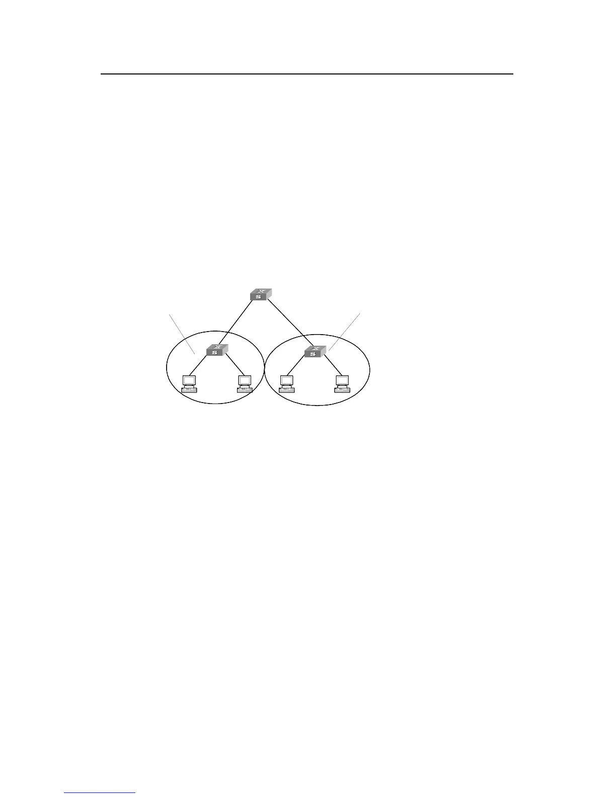
II. Networking diagram
2.4 isolate-user-vlan Configuration Example
I. Networking requirements
Switch A is connected to Switch B and Switch C in the downstream. The VLAN5 carried
by Switch B is the isolate-user-vlan, including the Uplink Ethernet1/1 and two
Secondary VLANs, VLAN2 and VLAN3. VLAN3 includes Ethernet0/1 and VLAN2
includes Ethernet0/2. The VLAN6 carried by Switch C is the isolate-user-vlan including
the Uplink Ethernet1/1 and two Secondary VLAN, VLAN3 and VLAN4. VLAN3 includes
Ethernet0/3 and VLAN4 includes Ethernet0/4. Seen from the Switch A, either Switch B
or Switch C carries one VLAN, VLAN 5 and VLAN 6 respectively.
Switch C
vlan 5
vlan 6
vlan 3
Switch A
E1/1
E0/3
E0/4
E1/1
Switch B
E0/1 E0/2
vlan 2
vlan 4
vlan 3
Figure 2-1 isolate-user-vlan configuration example
III. Configuration procedure
uration procedure of the Switch B and Switch C.
# Configure isolate-user-vlan
er-vlan enable
[Quidway-vlan5] port ethernet1/1
et0/1
[Quidway-vlan3] vlan 2
[Quidway-vlan2] port ethernet0/2
r-vlan to Map the Secondary VLAN
Hereafter only listed the config
Configure Switch B:
[Quidway] vlan 5
[Quidway-vlan5] isolate-us
# Configure Secondary VLAN
[Quidway-vlan5] vlan 3
[Quidway-vlan3] port ethern
# Configure the isolate-use
[Quidway-vlan2] quit
[Quidway] isolate-user-vlan 5 secondary 2 to 3
 Loading...